Apparatus and method for comminuting glass fibers

a technology of comminution and glass fibers, applied in the field of comminution apparatus and method of glass fibers, can solve the problems of large amount of comminution and recycling, lack of effective and convenient recycling opportunities in many areas, and the discharging of glass following its intended us

Inactive Publication Date: 2000-03-07
R & J HANSEN L L C
View PDF11 Cites 23 Cited by
  • Summary
  • Abstract
  • Description
  • Claims
  • Application Information

AI Technical Summary

Problems solved by technology

Although the unique properties of glass render it suitable for use in a variety of applications, disposal of glass following its intended use presents some significant problems.
One factor limiting the amount of recycling which is done is the lack of effective and convenient recycling opportunities in many areas.
These requirements, combined with the relative high cost of transporting cullet, make it difficult to produce high-quality cullet at a price which renders viable the recycling of glass.
Respiratory fibers are fine fibers having sharp, splintered ends which are inhaled into the lungs and which can harm the sensitive lung tissues.
Long-term exposure to respiratory fibers can be extremely hazardous to ones health.
Because of the risks associated with producing respiratory fibers, manufacturers of glass fiber dispose of the glass rather than grind and recycle it.
Because of the limited options for recycling glass, most scrap glass is disposed of merely by discarding it.
Because no viable method of recycling glass presently exists, large quantities of waste glass, including glass fiber, are generated annually which contribute to the filling of landfills.

Method used


Image

  • Apparatus and method for comminuting glass fibers
  • Apparatus and method for comminuting glass fibers
  • Apparatus and method for comminuting glass fibers

Examples


Embodiment Construction

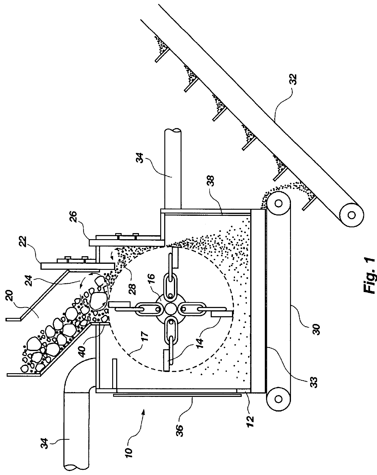
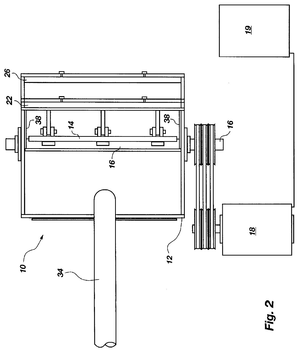
The present invention is directed to an apparatus for comminuting glass to produce glass particles having non-uniform, rounded edges. A cross-sectional side view of one currently preferred embodiment is shown in FIG. 1. The glass comminuting apparatus 10 includes a housing 12 within which a plurality of hammers or weighted members 14 rotate. The weighted members 14 are flexibly connected to a rotatable shaft 16 which extends within the housing 12. The weighted members are preferably evenly spaced around the shaft and attached to the shaft by chain links. A motor 18 (shown in FIG. 2) is connected to the shaft 16 to rotate the shaft. When the shaft 16 rotates, the weighted members 14 define a rotation circumference 17, shown as a dashed line in FIG. 1.

A variable speed controller 19 is preferably provided to vary the speed of motor 18. Although the motor 18 illustrated in FIG. 2 is preferably a 10 hp, variable speed motor, one skilled in the art will appreciate that the required motor ...


PUM

PropertyMeasurementUnit
hammer radiusaaaaaaaaaa
weightaaaaaaaaaa

Abstract

An apparatus for comminuting glass fibers is disclosed. Within a housing are a plurality of weighted members or hammers, flexibly connected to and spaced about a rotatable shaft. A drive member rotates the hammers about the shaft to define a rotation circumference. A glass intake opening located at the top portion of the housing is provided to introduce glass fibers and carrier material into the apparatus. A first adjustable plate is located adjacent the glass intake opening and positioned to provide a space between the first adjustable plate and the hammers' rotation circumference. A first glass suspension chamber is defined by the glass intake opening, the first adjustable plate, and the rotation circumference of the hammers. In operation, a quantity of glass fibers and carrier material is introduced into the apparatus, and spinning weighted members contact the glass, causing the glass to strike the first adjustable plate and other glass particles. Adjusting the space between the first adjustable plate the weighted members' rotation circumference helps control the resulting particle size of the comminuted glass. Controlling the shaft rotation speed affects the resulting particle size of the comminuted glass.

Description

The present invention relates to an apparatus and method for safely comminuting glass fibers and fine glass particles to produce comminuted glass fibers, particles and powder having non-uniform, rounded edges. Advantageously, non-respiratory glass fibers are comminuted with little or no respiratory fibers being produced according to the present invention. In addition, the present invention generally converts respiratory fibers into a safe form.TECHNICAL BACKGROUNDBecause the raw materials from which glass is made are indigenous to most areas of the world and are generally inexpensive, glass has become an important material for a variety of applications. Even with the proliferation of plastics, glass continues to be the material of choice for use in making many types of containers and windows. Indeed, millions of tons of glass are produced annually.Although the unique properties of glass render it suitable for use in a variety of applications, disposal of glass following its intended...

Claims


Application Information

Patent Timeline
Patent Type & Authority Patents(United States)
IPC IPC(8): B02C13/04B02C13/00C03B37/16C03B37/10C03C1/00C03C1/02B02C19/00
CPCB02C13/04B02C19/0087C03B37/16C03C1/002C03C1/024B02C2013/2816Y02W30/60
Inventor HANSEN, RICHARD W.
Owner R & J HANSEN L L C
Why Eureka
Try Eureka