

Segmented cutting tools
a cutting tool and segmental technology, applied in the direction of gear teeth, manufacturing tools, manufacturing apparatus, etc., can solve the problems of only partially effective solution, deviation from the desired drilling direction, and slower cutting operation
- Summary
- Abstract
- Description
- Claims
- Application Information
AI Technical Summary
Benefits of technology
Problems solved by technology
Method used
Image

Examples
example 1
In this Example a drill core bit was prepared using segments made and placed according to the invention. This bit was compared with a drill core bit of exactly the same design except that the segments were not hardened along one side. The performance of the two bits was compared in side-by side-testing.
In each case the bond used was a 70 / 30 wt % blend of cobalt / bronze and the abrasive grit was 30 / 40 mesh diamond from DeBeers with a grade of SDA 100+. The amount of diamond in the segments was set at 10 vol %. Segments made from this bond / grit mixture had a 3 mm kerf and a 24 mm length. Nine such segments were brazed to a body member to provide a conventional 10.1 cm diameter core drill bit.
A similar accordance with (with modified segments in accordance with the invention), was made by brazing modified segments to the same type of body member. The modified segments were made by placing a thin layer of 36 grit seeded sol-gel alumina filamentary abrasive particles on one surface of the ...
example 2
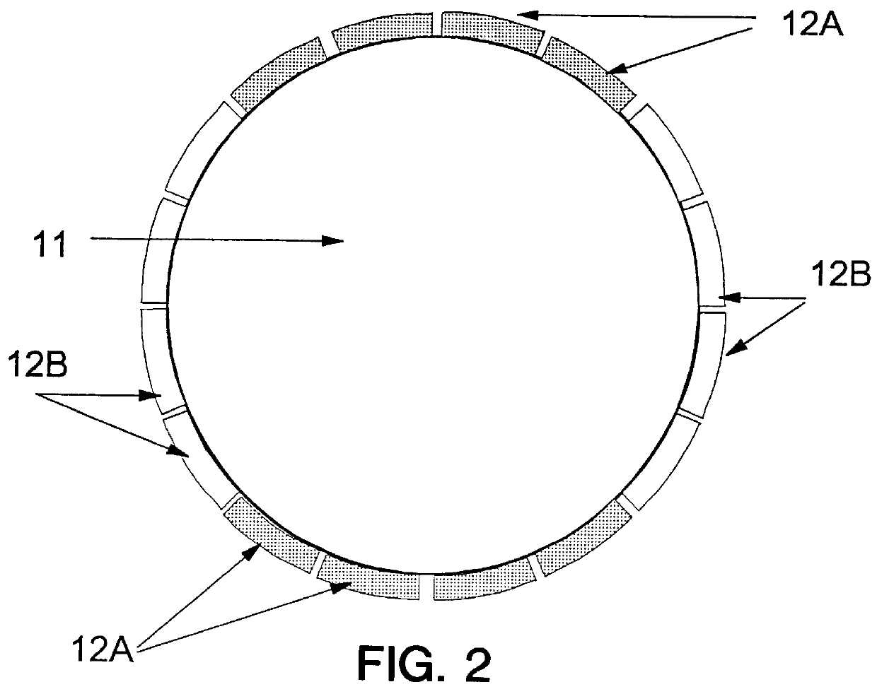
This Example shows the advantage of the invention when applied to a segmented wheel rather than a core drill bit as used in Example 1.
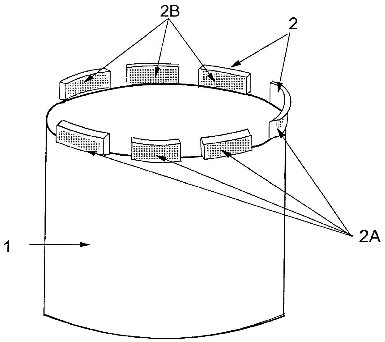
Such a segmented wheel is illustrated in FIG. 2 which shows a body member, 11, in the form of a metal disc with, laser welded to the circumference of the wheel, a plurality of spaced segments, 12, which had each been hardened on one surface using a coating of abrasive grits exactly as described in Example 1. The hardened surfaces are arranged in groups such that four consecutive segments have the hardened surface facing the viewer, marked 12A, coated and the next four, marked 12B, have the hardened surface on the opposite side from the viewer coated, and so on around the circumference of the wheel.
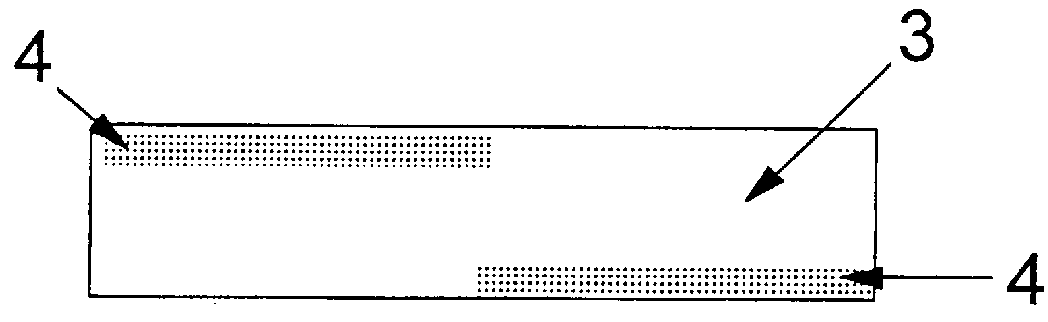
The wheel actually used in this Example 2 however had the coatings arranged somewhat differently. Each segment had half of each side coated such that on one side the left hand half was coated while on the other side, the opposite end was coated. This resulte...
example 3
In this Example a drill core bit according to the invention is compared with a standard drill core bit. The standard (control) drill bit had superabrasive uniformly distributed throughout the segment and no surface was hardened. The drill core bit according to the invention had all the outside surfaces of the segments hardened using the ceramic alumina abrasive grain used in Example 1.
In each case the bond was 100% bronze, the diamond was 35 / 40 mesh DeBeers SDA 100+ grade and represented 8.75% of the volume of the segment. The segments had a 4 mm kerf and were 24 mm long. Nine segments were located around the periphery of the 10.1 cm diameter core bit body member.
For each blade a total of 20 cuts were made to a depth of 250 mm in a medium hard cured concrete (5,000 psi) with three 16 mm rebars. Each cut cut through all three rebars. The drill used was a Milwaukee 2.2 KW drill drawing 11 amps and rotating at 600 rpm. The results obtained were as follows:
As can be seen the test bit ac...
PUM
| Property | Measurement | Unit |
|---|---|---|
| diameter | aaaaa | aaaaa |
| diameter | aaaaa | aaaaa |
| length | aaaaa | aaaaa |
Abstract
Description
Claims
Application Information