Hermetic sealing of a substrate of high thermal conductivity using an interposer of low thermal conductivity

Inactive Publication Date: 2000-03-14
IBM CORP
View PDF18 Cites 17 Cited by
  • Summary
  • Abstract
  • Description
  • Claims
  • Application Information

AI Technical Summary

Benefits of technology

Conventional seam sealing of metal lids is generally done on low thermal conductivity substrates such as alumina and glass-ceramic. The pulse current applied to the electrodes is in short time intervals (millisecs).
It was found that by pre-brazing the thermal interposer 23, with the solder / braze layer 13, onto the seal band 19, the heat dissipation into the aluminum nitride (AlN) substrate 10, was significantly reduced during the seam sealing process.
It was discovered that the thermal interposer 23, not only significantly slowed down the heat transfer into the AlN substrate 10, allowing for reproducible hermetic sealing, but also acted as a stress reducer at the substrate / braze interface.
The use of the thermal interposer 23, pre-brazed onto the seal ring 19, on the AlN substrate 10, also allows for uniform localized reflow of the braze preform 15, which is attaches the thermal cap or lid 20, to the interposer 23, during the seam seal process.
As stated earlier that this happens because the heat dissipation into the AlN 10, is substantially decreased due to the relatively poor thermal conductivity of the thermal interposer 23. This allows for the complete wetting of the interposer 23, and lid surfaces 20, by the braze preform 15, insuring good hermeticity.

Problems solved by technology

Process improvements alone are not sufficient to improve both yield and reliability.
These conventional alumina substrates, such as, based on ceramics or glass-ceramics packages, have relatively poor thermal conductivity, making it easy to do the localized heating required to reflow the solder / braze joint using the seam seal process.
However, aluminum nitride (AlN) substrates, by design have a relatively high thermal conductivity, making it extremely difficult to maintain sufficient localized heating to complete the wetting / reflow of braze / solder joint between a thermal cap or lid and the seal ring metallization on the AlN substrate.

Method used


Image

  • Hermetic sealing of a substrate of high thermal conductivity using an interposer of low thermal conductivity
  • Hermetic sealing of a substrate of high thermal conductivity using an interposer of low thermal conductivity

Examples


example 1

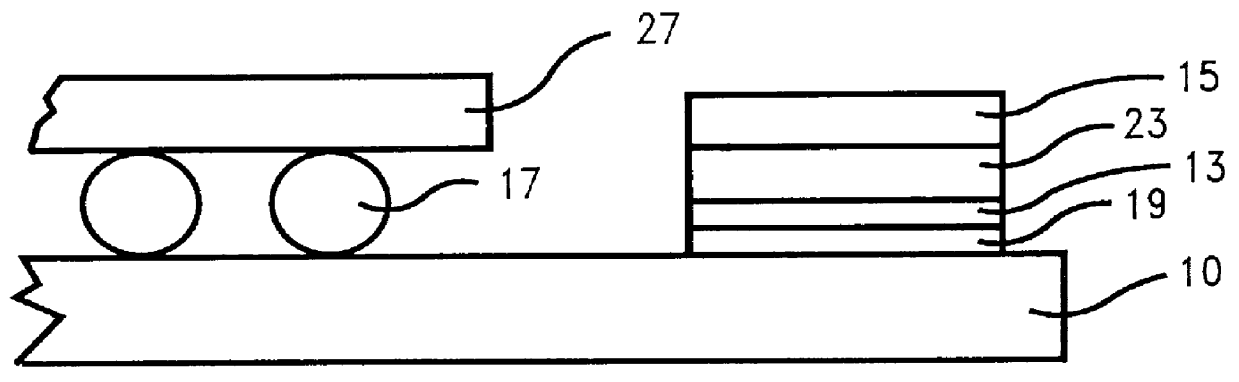
Aluminum nitride packages without the thermal interposer 23, where prepared using the standard seam seal process and tested for hermeticity. All of these packages failed in the liquid to liquid (-65.degree. C. to 150.degree. C.) test.

Upon further testing it was discovered that in trying to seam seal the metal lid 20, onto AlN substrate 10, that as soon as any of the braze or solder material got to it's liquidus state a perfect thermal conduction path was created for the rapid dissipation of heat into the AlN substrate 10, resulting in an incomplete filleting or wetting between the seal band 19, and the interposer 23. The TCE of the AlN substrate 10, was about 3.4 E-6 ppm.

example 2

Aluminum nitride packages 25, with the thermal interposer 23, where prepared using the seam seal process of this invention and tested for hermeticity, using the liquid to liquid (-65.degree. C. to 150.degree. C.) test. The AlN packages 25, with the thermal interposers 23, were still hermetic even after over 2,000 cycles.

The TCE of Alloy 42 used was about 4.3 E-6 ppm, while the TCE of the AlN substrate 10, was about 3.4 E-6 ppm.


PUM


Abstract

The present invention relates generally to a new process for hermetically sealing of a high thermally conductive substrate, such as, an aluminum nitride substrate, using a low thermally conductive interposer and structure thereof. More particularly, the invention encompasses a hermetic cap which is secured to an aluminum nitride substrate using the novel thermal interposer. The novel thermal interposer basically comprises of layers of relatively high thermal conductive metallic materials sandwiching a core layer of low thermal conductive metallic material.

Description

The present invention relates generally to a new process for hermetically sealing of a high thermally conductive substrate, such as, an aluminum nitride substrate, using a low thermally conductive interposer and structure thereof. More particularly, the invention encompasses a hermetic cap which is secured to an aluminum nitride substrate using the novel thermal interposer. The novel thermal interposer basically comprises of layers of relatively high thermal conductive metallic materials sandwiching a core layer of low thermal conductive metallic material.Semiconductor devices are becoming smaller and more dense with the evolution of new technology. However, increases in circuit density produce a corresponding increase in overall chip requirements to remain competitive. Chip manufacturers are therefore challenged to improve the quality of their products by identifying new ways of improving their manufacturing processes and material used to make their products. Whereas significant im...

Claims


Application Information

Patent Timeline
IPC IPC(8): H01L23/10H01L23/02
CPCH01L23/10H01L2224/16H01L2924/01079H01L2924/09701H01L2924/16152H01L2924/163H01L2924/00014H01L2224/0401
Inventor INTERRANTE, MARIO J.ECONOMIKOS, LAERTISHERRON, LESTER WYNN
Owner IBM CORP
Why Eureka
Try Eureka