Shutoff valve assembly

Inactive Publication Date: 2000-03-21
WESTINGHOUSE AIR BRAKE CO
View PDF5 Cites 11 Cited by
  • Summary
  • Abstract
  • Description
  • Claims
  • Application Information

AI Technical Summary

Benefits of technology

Another object of the present invention is to reduce the number of fault-prone connections along a trainline which passes from railway vehicle to railway vehicle down the length of a train.

Problems solved by technology

This system is inconsistent with the industry standard brake line fluid pressure connector.
This is a combined fluid pressure connector and electrical connector which is inconsistent with the industry standard brake line fluid pressure connector.
None of the applications cited above provide means for connection of electrical or electronic systems on a railway vehicle to electrical trainline cables connected between railway vehicles.

Method used


Image

  • Shutoff valve assembly
  • Shutoff valve assembly
  • Shutoff valve assembly

Examples


Embodiment Construction

, particularly, when the detailed description is taken in conjunction with the attached drawing figures and with the appended claims.

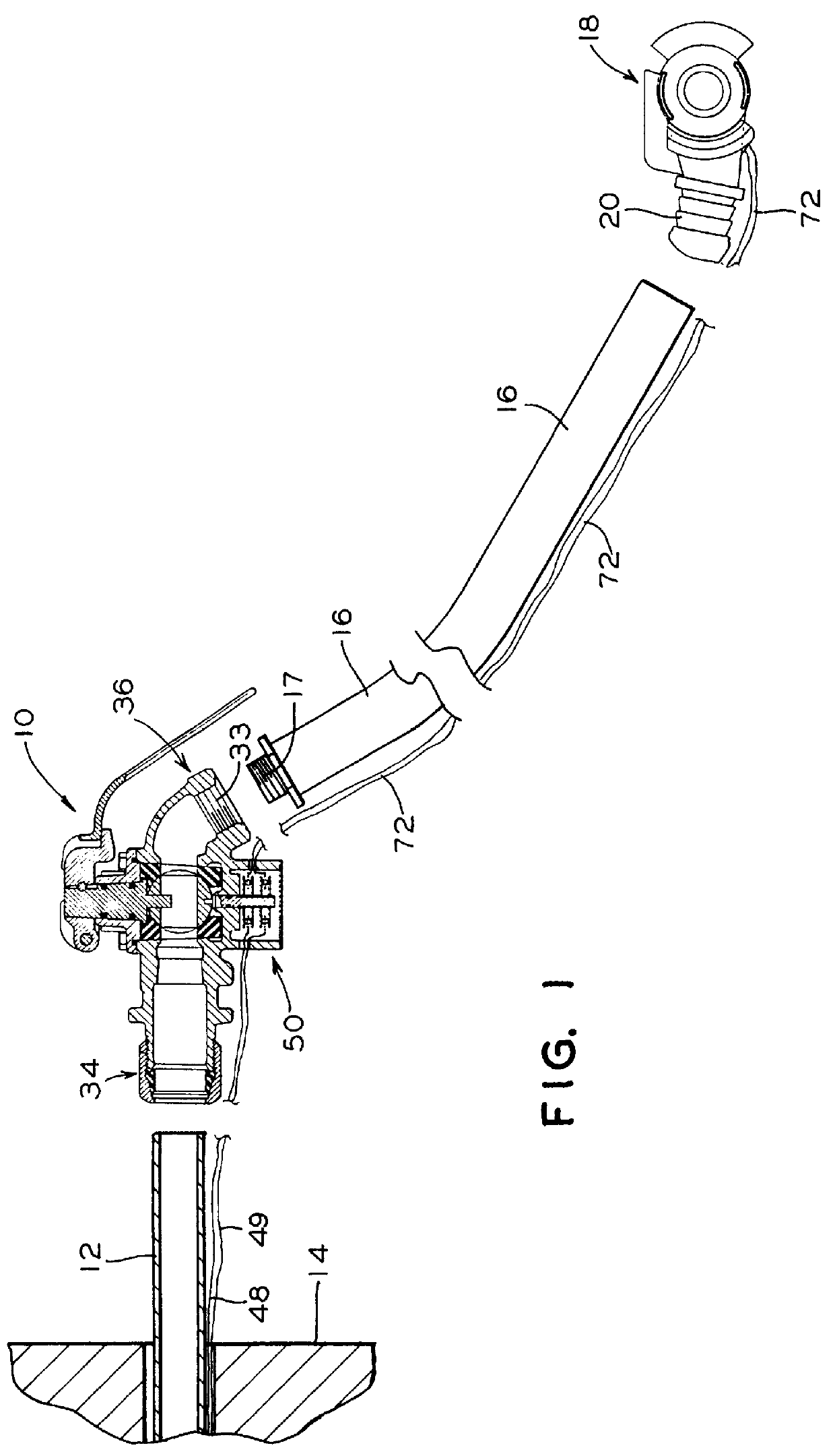
FIG. 1 shows a brake line shutoff valve assembly which includes an electrical switch, the assembly for mounting on a railway vehicle.

FIG. 2A shows a gladhand assembly of the prior art which connects both the pneumatic brake lines and electrical trainlines of two coupled railway vehicles, viewed from a direction opposite the mating surface of the gladhand assembly.

FIG. 2B shows a sectional drawing of the gladhand assembly.

FIG. 2C shows a view of the gladhand looking toward the mating surface.

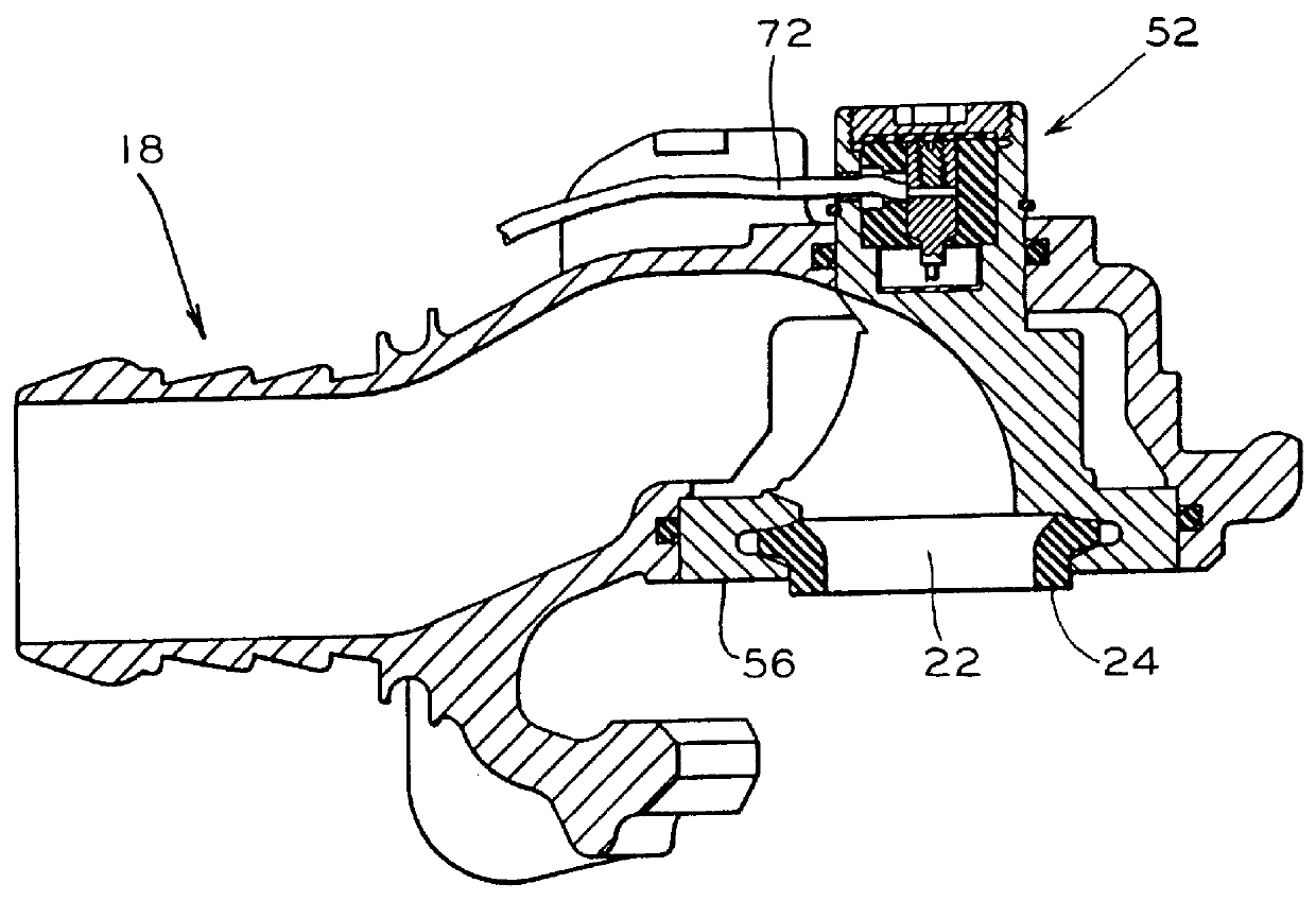
FIG. 3 shows the valve assembly in detail.

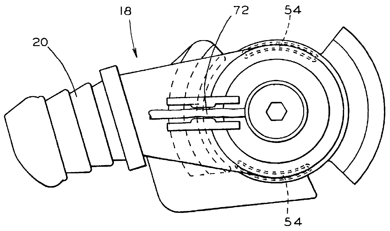
FIG. 4 shows an exploded view of the switch portion of the valve assembly.

FIG. 5 shows a valve assembly which includes a junction box for joining electrical conductors to equipment on the train to the electrical trainline.

FIG. 6A shows the electric line attachment sites in the junction box.

FIG. 6B shows a side view of one of...


PUM


Abstract

A railroad brake line shutoff valve assembly for connecting a car mounted railway brake line to a brake line air hose. The assembly includes a shutoff valve with a stationary valve portion and a moveable valve portion. The stationary valve portion has a first fluid line attachment site and a second fluid line attachment site. Movement of the moveable valve portion to one position opens a flowpath through the valve between the first fluid line attachment site and the second fluid line attachment site. Movement of the moveable valve protion to another position closes the flowpath through the valve. The assembly includes a junction box having a first set of electric line attachment sites for connection of a set of car mounted electrical trainline conductors mounted on the railway vehicle and a second set of electric line attachment sites for connection of a set of electrical line end segments which terminate in a multiple contact electrical trainline connector. The junction box also has a third set of electric line of at least one of an electronic system or an electrical system located on the railway vehicle. Each member of the first set of electric line attachment sites is electrically connected to a corresponding member of the second set of electric line attachment sites and also to a corresponding member of the third set of electric line attachment sites.

Description

The present invention relates, in general, to a shutoff valve for a railroad brake line and to a junction box for attachment of railroad car electrical and electronic systems.The following five United States patents relate to the art of making electrical connections between electric lines in adjacent railway cars.U.S. Pat. No. 3,251,480, issued to K. L. DePenti et al on May 17, 1966. This patent provides a connector for automatic connection of fluid pressure conduits and electrical circuits. The connector is located underneath the coupler and joining of the connectors is intended to occur automatically as the cars are coupled. This system is inconsistent with the industry standard brake line fluid pressure connector. No redundancy of contacts is provided, nor wiping action.U.S. Pat. No. 3,646,498, issued to R. T. Reed et al on Feb. 29, 1972. This is an electrical connector which is not associated with a fluid pressure connector. Electrical contacts are embedded in insulating blocks,...

Claims


Application Information

Patent Timeline
IPC IPC(8): B61G5/00B61G5/08B60T17/04B60T17/00
CPCB60T17/043B61G5/08
Inventor ENGLE, THOMAS E.
Owner WESTINGHOUSE AIR BRAKE CO
Why Eureka
Try Eureka