Vibrator

a technology of pneumatic vibrators and vibrators, which is applied in the field of pneumatic vibrators, can solve the problems of increasing cost and, therefore, selling price, and requiring a large amount of machining over the course of manufacture, and achieves the effects of enhancing cooling features, facilitating service, and enhancing mounting flexibility

Inactive Publication Date: 2000-04-04
VENTUREDYNE LTD
View PDF14 Cites 19 Cited by
  • Summary
  • Abstract
  • Description
  • Claims
  • Application Information

AI Technical Summary

Benefits of technology

Another object of the invention is to provide a pneumatic vibrator which affords a greater degree of mounting flexibility than certain types of known vibrators.
Another object of the invention is to provide a pneumatic vibrator which is easy to service, i.e., repair.
Yet another object of the invention is to provide a pneumatic vibrator which has enhanced cooling features.
Further, the boundary surface is substantially planar and the impact block includes a substantially planar block surface against the boundary surface. The maximum dimension of the perimeter portion, measured in a direction normal to the housing central axis, is somewhat less than the maximum dimension of the cavity measured in the same fashion. And, measured in the same fashion, the maximum dimension of the central portion of the impact block is somewhat less than the inside dimension of the sleeve adjacent to such central portion. The resulting air-circulating spaces and the slightly increased overall surface area of the aforedescribed impact block (as compared to a plain disc-shaped block of uniform dimension) affords a degree of cooling not otherwise available or at least not as easily available.
In yet other aspects of the invention, the vibrator wall has a terminus spaced from the boundary surface. A cap is affixed to the housing at the terminus and the sleeve is compressed between the cap and the impact block. To state it another way, the cap is bolted to the housing and the vibrator housing, sleeve and cap are configured and dimensioned in such a way that the cap compresses against the sleeve before the cap "bottoms out" on the terminus. Such construction helps assure that the sleeve and impact block are firmly secured in their respective locations in the housing cavity.

Problems solved by technology

While these prior art vibrators are understood to have been generally satisfactory for their intended purposes, they are not without disadvantages.
One involves seeming lack of flexibility in mounting and use.
Another seeming disadvantage of prior art vibrators is that they require a good deal of machining over the course of manufacture.
Of course, this adds incrementally to cost and, therefore, to selling price.
Yet another seeming disadvantage is that the designers of such vibrators have not fully appreciated how to make the vibrator more easily serviceable.

Method used


Image

  • Vibrator
  • Vibrator
  • Vibrator

Examples


Embodiment Construction

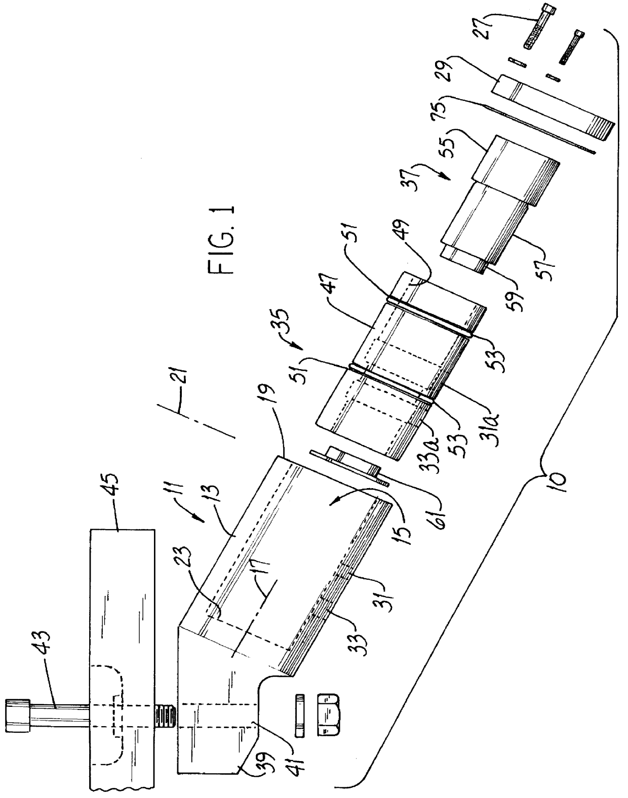
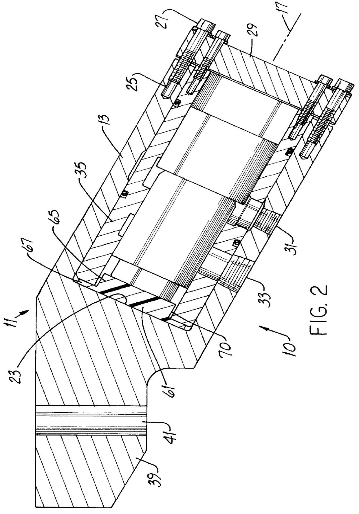
Referring to FIGS. 1-4, the new vibrator 10 has a housing 11 comprising a wall 13 of substantially uniform thickness and extending around and partially defining a cylindrical cavity 15. The cavity 15 is substantially concentric with the vibrator long axis 17. The wall 13 has a terminus 19 which, in a specific embodiment, is an annulus coincident with a plane 21 perpendicular to the axis. A substantially planar cavity floor or boundary surface 23 extends to the wall 13 and also partially defines the cavity 15.

Holes 25 for fasteners 27 are drilled or otherwise formed in the wall 13 in a direction parallel to the axis 17. As further described below, such holes 25 and fasteners 27 secure a cap 29 to the housing 11. Threaded inlet and exhaust ports 31 and 33, respectively, are radially formed in the wall 13. Most preferably, the housing 11 (as well as the sleeve 35 and the piston 37 described below) are made of metal, e.g., aluminum or cast iron.

The housing 11 also includes an angled nos...


PUM


Abstract

A vibrator has (a) a housing including a wall forming a cavity, (b) a sleeve in the cavity, and (c) a piston received in the sleeve for reciprocating movement therein. In the improvement, the cavity has a boundary surface inside the housing and the vibrator includes an impact block interposed between the boundary surface and the sleeve. Such impact block is positionally retained in the cavity by the boundary surface and the sleeve.

Description

This invention relates generally to measuring and testing and, more particularly, to such measuring and testing using a vibrator to "shake" a table supporting the apparatus being tested.Certain types of measuring and testing involve mounting the product to be tested upon a platform or table capable of limited movement in one or more axes of motion. The table is shaken or vibrated using a fluid vibrator, usually pneumatic as opposed to hydraulic, coupled to the table. An example of such an arrangement is disclosed in U.S. Pat. No. 5,365,788 (Hobbs) and involves a table vibrated by what the patent calls exciters.Vibrators (or exciters) are available in a variety of configurations. Manufacturers of pneumatic vibrators include Cleveland Vibrator Co., Cleveland, Ohio, and Martin Engineering Co., Neponset, Ill. The Model VMS vibrator made by Cleveland Vibrator Co. includes a chrome-plated piston movable in a housing. At one end, the housing is closed by a bolted cap and the other end of t...

Claims


Application Information

Patent Timeline
Patent Type & Authority Patents(United States)
IPC IPC(8): G01M7/06G01M7/00G01M7/04
CPCG01M7/06G01M7/04
Inventor BRIGGS, MARK W.WETZEL, JOSEPH D.
Owner VENTUREDYNE LTD
Why Eureka
Try Eureka