Mobile communication system and base station apparatus therefor

a technology which is applied in the field of mobile communication system and base station apparatus therefor, can solve the problems of uneconomical and unpreferable multiple system, unsatisfactory use demand, and inability to meet the needs of users, so as to improve economics and alleviate the poor appearance of a building

Inactive Publication Date: 2000-04-04
KK TOSHIBA
View PDF15 Cites 56 Cited by
  • Summary
  • Abstract
  • Description
  • Claims
  • Application Information

AI Technical Summary

Benefits of technology

It is, therefore, an object of the present invention to provide a mobile communication system and a base station apparatus therefor, which can prevent base stations of a plurality of mobile communication networks from being equipped to overlap each other, and can improve economy and alleviate poor appearance of a building or the like.
It is another object of the present invention to provide a mobile communication system and a base station apparatus therefor, which can improve the use efficiency of lines connected to a public digital network even in an area with a low traffic density and hence, can improve the use efficiency of lines.

Problems solved by technology

However, the above-mentioned system suffers the following problems.
However, in an area with a low traffic density like in the provinces or suburbs, not so many use demands are assured.
For this reason, it is very uneconomical to equip base stations in units of service providers.
Therefore, such multiple systems are very unpreferable since not only they are uneconomical but also they pose another problem, e.g., they spoil the appearances of the sales floors of the department store.

Method used


Image

  • Mobile communication system and base station apparatus therefor
  • Mobile communication system and base station apparatus therefor
  • Mobile communication system and base station apparatus therefor

Examples


first embodiment

(First Embodiment)

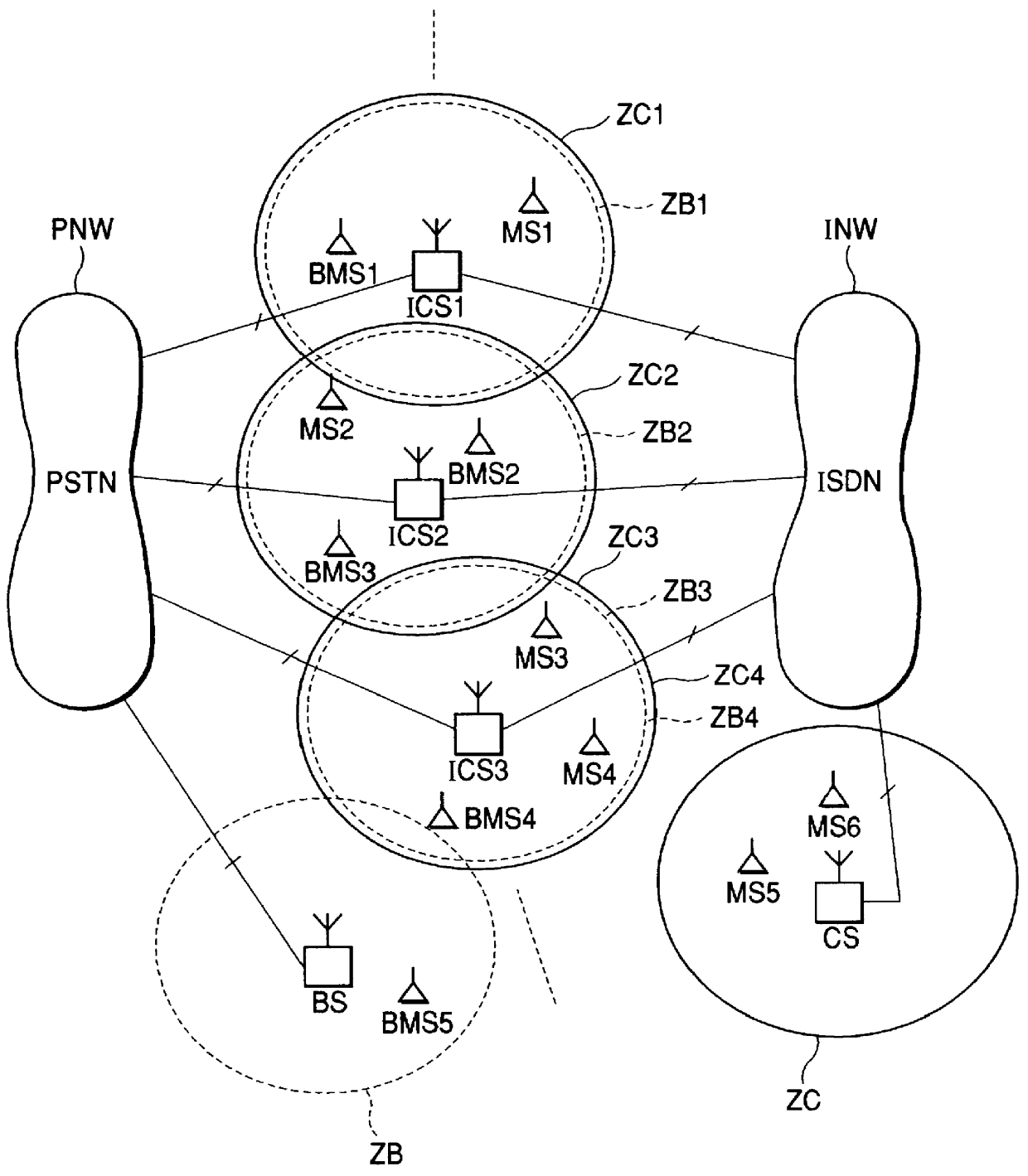
FIG. 2 is a schematic diagram showing the arrangement of a mobile communication system according to the first embodiment of the present invention. In the system of this embodiment, a private system and a public system are built in a common service area, and a plurality of shared base stations ICS1, ICS2, . . . are distributed and arranged in the service area. These shared base stations ICS1, ICS2, . . . respectively form radio zones ZB1, ZB2, . . . for the private system, and radio zones ZC1, ZC2, . . . for the public system.

The shared base stations ICS1, ICS2, . . . are connected to an analog telephone network (PSTN) PNW via a plurality of analog subscriber's lines, and are also connected to an integrated services digital network (ISDN) INW via a plurality of ISDN subscriber's lines.

Mobile stations BMS1, BMS2, . . . for the private system, and mobile stations MS1, MS2, . . . for the public system are radio-connected to the shared base stations ICS1, ICS2, . . . by...

second embodiment

(Second Embodiment)

In this embodiment, a pair of slots of the three pairs of communication slots in the TDMA-TDD frame are assigned as slots exclusively used for the private system, and with this arrangement, even when the traffic of the public system increases, a communication channel for the private system can be assured.

FIG. 7 is a view showing the assignment state of communication slots by the system of this embodiment. Referring to FIG. 7, the third slots of three pairs of communication slots in one frame are assigned as those exclusively used for the private system. Therefore, a mobile station MS of the public system performs a communication by selecting one of the first and second slots except for the third slots of the three pairs of communication slots in one frame upon placing an outgoing call or receiving an incoming call. Therefore, even when the traffic of the public system increases, a mobile station BMS of the private system can be prevented from being always busy.

On ...

third embodiment

(Third Embodiment)

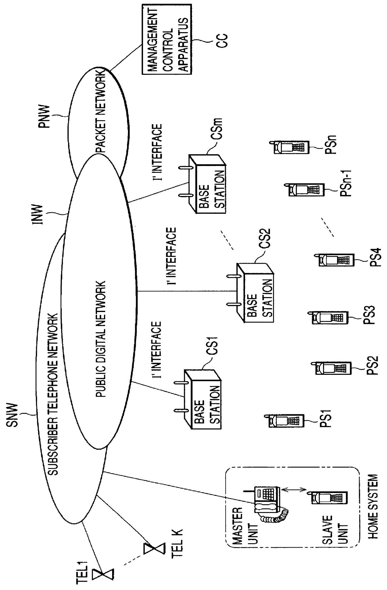
FIG. 13 is a schematic diagram showing the arrangement of a mobile communication system according to the third embodiment of the present invention.

Of a plurality of base stations which are distributed in a service area, for example, a plurality of base station groups CSa1 and CSa2, which are equipped in areas with a low traffic density, are respectively accommodated in integrated control apparatuses ISa1 and ISa2 via I, lines, and are respectively connected from these integrated control apparatuses ISa1 and ISa2 to a public digital network INW via I' lines. At this time, the number of I' lines connecting one of the integrated control apparatuses ISa1 and ISa2 and the public digital network INW is set to be smaller than a total number of I' lines required for connecting the base stations CSa1, CSa1, . . . to the integrated control apparatus ISa1 or ISa2.

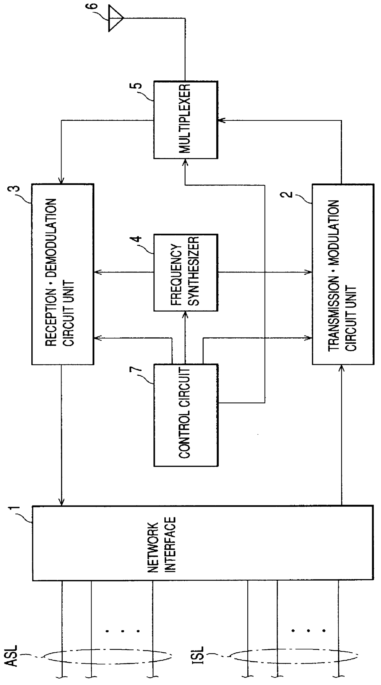
The integrated control apparatuses ISa1 and ISa2 have the following arrangement. FIG. 14 is a block diagram showin...


PUM


Abstract

PCT No. PCT / JP96 / 01126 Sec. 371 Date Dec. 30, 1996 Sec. 102(e) Date Dec. 30, 1996 PCT Filed Apr. 25, 1996 PCT Pub. No. WO96 / 35307 PCT Pub. Date Nov. 7, 1996In a mobile communication system according to this invention, an integrated control apparatus (ISa1) is arranged between a plurality of base stations (CSa1, CSa1, . . . ) arranged in an area with a low traffic density, and a public digital network (INW), the integrated control apparatus (ISa1) accommodates I' lines of the base stations (CSa1, CSa1, . . . ), the integrated control apparatus (ISa1) and the public digital network are connected via I' lines having a smaller number of channels than the total number of channels of the I' lines, and the integrated control apparatus (ISa1) performs various kinds of control for call origination / termination with the base stations (CSa1, CSa1, . . . ).

Description

The present invention relates to a mobile communication system and a base station apparatus therefor and, more particularly, to a mobile communication system in which a plurality of mobile communication networks independently operate in a common service area, and a base station apparatus therefor.In recent years, systems that adopt microcells (e.g., PHS (Personal Handyphone System) in Japan) of digital mobile communication systems have been put into practical applications.In such system using microcells, the size of the area covered by one base station is as small as a radius of 100 to 200 meters, and the subscriber accommodation capability is improved by increasing the frequency reuse efficiency.The above-mentioned system includes a public system built to cover a wider area including a public area by connecting to a public digital network, and a private system built in home, an office, or the like to have a private branch exchange as a core. In the public system, a plurality of ser...

Claims


Application Information

Patent Timeline
Patent Type & Authority Patents(United States)
IPC IPC(8): H04Q7/30H04Q7/38H04Q7/24H04B7/005H04Q7/26H04Q7/36H04W16/10H04W16/14H04W52/04H04W88/10H04W92/02H04W92/12
CPCH04W88/10H04W16/10H04W16/14H04W92/12H04W92/02H04W52/04
Inventor SAKAMOTO, MASAYUKIIWASAKI, KAZUNORISEKIYA, KUNIHIKOYAMAGISHI, KATSUMITATEISHI, TORUMURANO, KATSUMIMIZUNO, TOMOO
Owner KK TOSHIBA
Why Eureka
Try Eureka