Multiple flavor beverage dispensing air-mix nozzle

a beverage and air-mix technology, applied in the field of beverage dispensing nozzles, can solve the problems of syrup carryover, standard drink dispensing nozzles failing to meet customer demand, and difficult to completely remove the residual syrup from a previously dispensed drink

Inactive Publication Date: 2000-04-11
LANCER PARTNERSHIP
View PDF5 Cites 83 Cited by
  • Summary
  • Abstract
  • Description
  • Claims
  • Application Information

AI Technical Summary

Benefits of technology

The most significant feature of the invention is the distribution of beverage syrup in a circumferential pattern around the exit end of the beverage dispensing nozzle, thus presenting the greatest surface area for contact with the mixing fluid. In the preferred embodiments, the momentum of the syrup as it exits the nozzle is controlled so that it is substantially equal to or less than the momentum of the mixing fluid to insure intimate mixing, while avoiding carbon dioxide breakout when the mixing fluid is carbonated water.
It is another object of the present invention to provide a beverage dispensing nozzle that eliminates stratification between the beverage syrup and mixing fluid.
It is further object of the present invention to provide a beverage dispensing nozzle that is capable of dispensing multiple flavors while preventing carryover between different flavored syrups.

Problems solved by technology

Due to increases in both the number of customers served and the volume of drinks dispensed by the food and drink service industry and counter space being at a premium, standard drink dispensing nozzles fail to meet customer demand.
One major problem encountered with multiple flavor nozzles is syrup carryover.
It is very difficult to completely remove the residual syrup from a previously dispensed drink to avoid carryover into a subsequent, different flavored drink.
This carryover causes problems with the flavor, the color, and the smell of dispensed drinks.
Even small amounts of carryover syrup which cause only minor problems with odor and taste have a significant effect on the color of clear drinks, which is undesirable.
Another problem that must be addressed is proper mixing of the mixing fluid, such as carbonated or plain water, and syrup, and, if desired, flavor additives.
Excessive foaming is another problem when the mixing fluid is carbonated water.
At high flow rates, out-gassing of carbon dioxide is particularly troublesome.
Consequently, as the carbonated water releases carbon dioxide in both the nozzle and the cup, the released carbon dioxide escaping solution causes excessive foaming of the dispensed beverage.
That excessive foaming creates a poor product because the drink is generally "flat".
Prior attempts to solve the aforementioned problems with multiple flavor nozzles have not been successful.
The total surface area of syrup presented for contact with the mixing fluid is relatively small; thus proper mixing is difficult.
The configuration also makes it difficult to eliminate syrup carryover.

Method used


Image

  • Multiple flavor beverage dispensing air-mix nozzle
  • Multiple flavor beverage dispensing air-mix nozzle
  • Multiple flavor beverage dispensing air-mix nozzle

Examples


Embodiment Construction

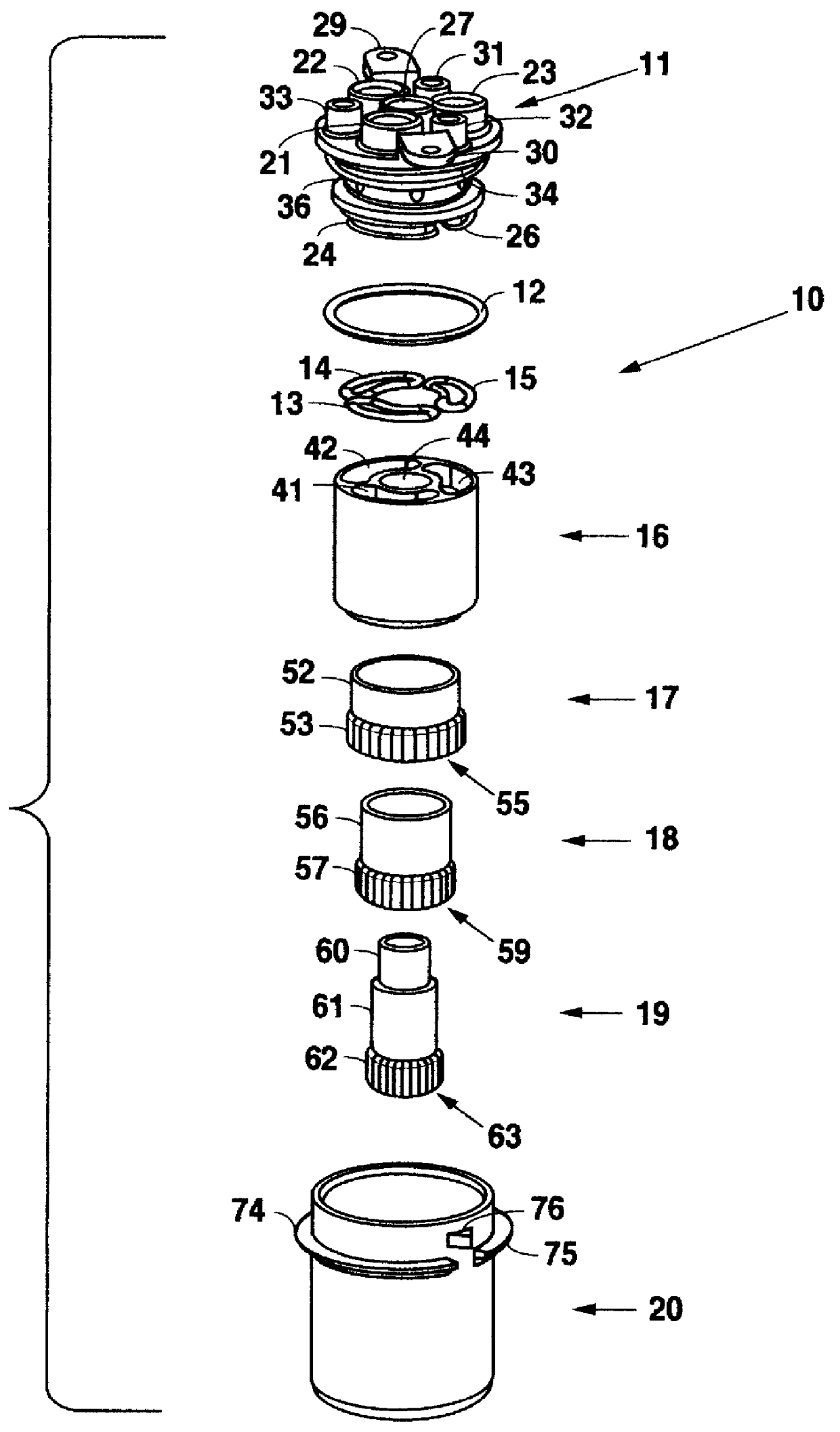
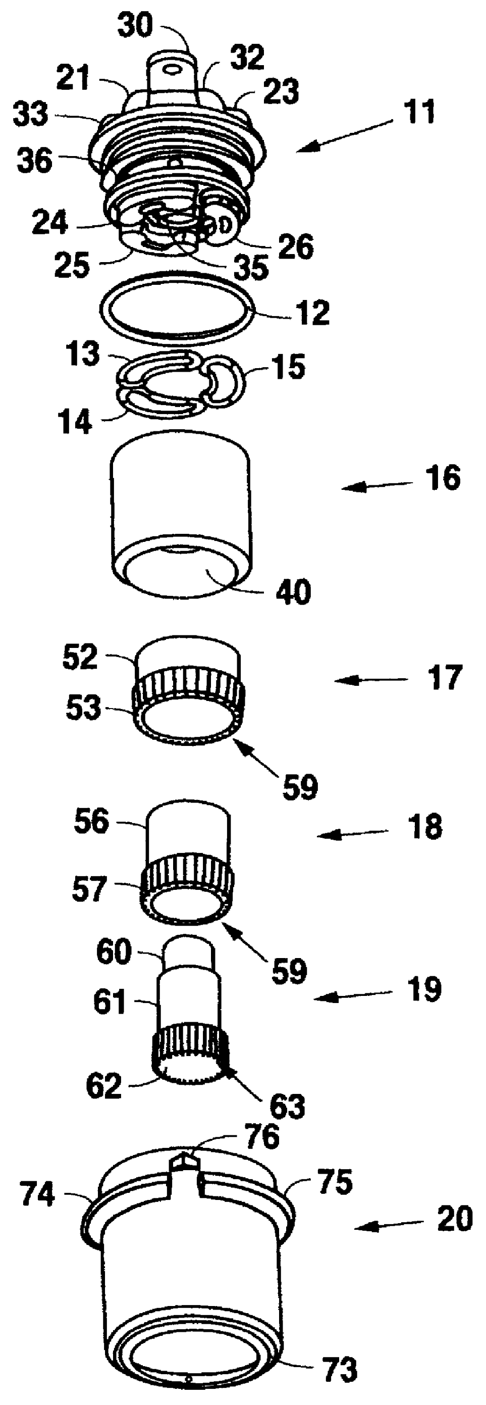
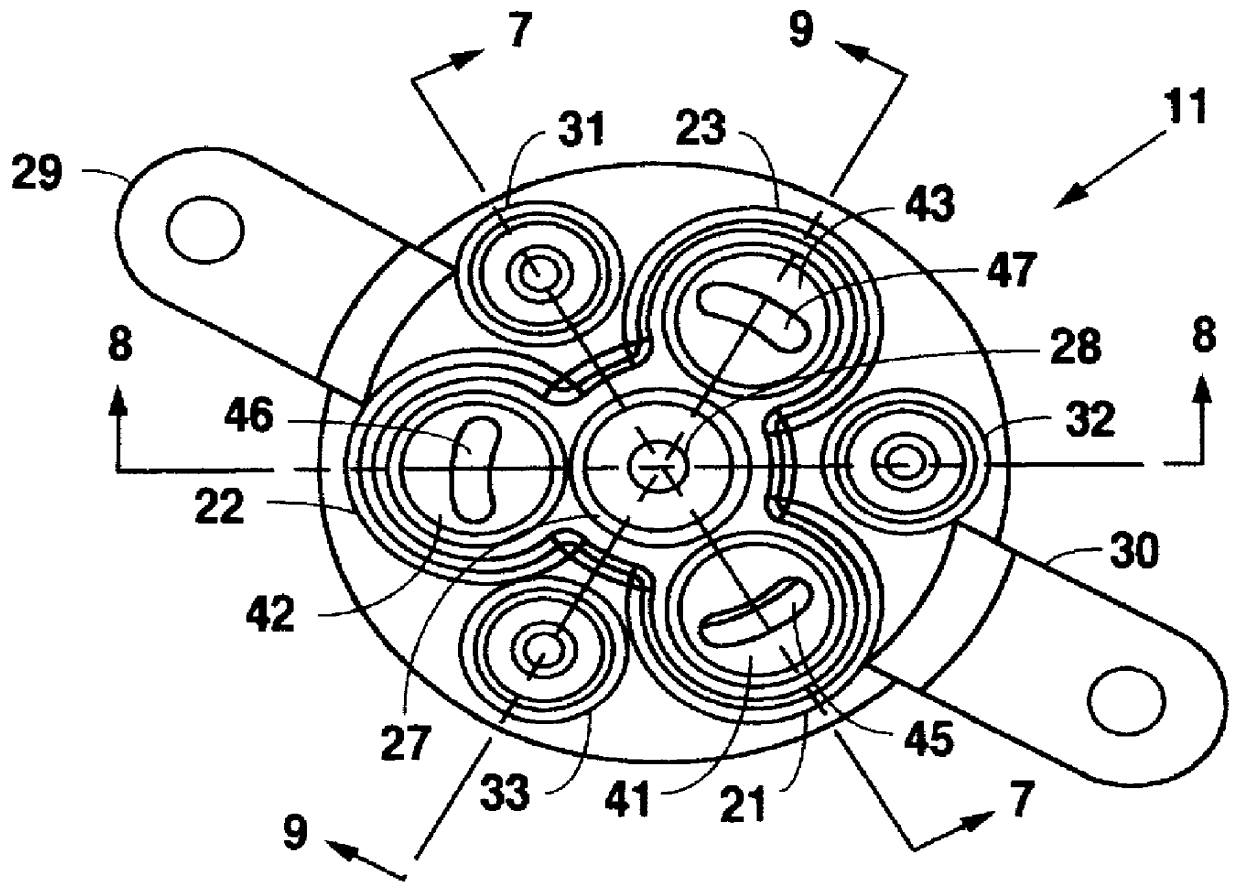
As illustrated in FIGS. 1-9, a beverage dispensing nozzle 10 includes a cap member 11, an o-ring 12, gaskets 13-15, an inner housing 16, a first or outer annulus 17, a second or intermediate annulus 18, a third or inner annulus 19, and an outer housing 20. The inner housing 16 defines a chamber 40 and includes an opening 44 into chamber 40. The inner housing 16 includes cavities 41-44 that communicate with the chamber 40 through conduits 45-47, respectively (refer to FIGS. 1 and 2). Even though the conduits 45-47 connect to separate cavities 41-43, they are concentrically spaced apart; namely, the conduit 47 is innermost, the conduit 45 is intermediate, and the conduit 46 is outermost (refer to FIGS. 7-9). The conduits 45-47 are concentrically spaced apart so that beverage syrup may enter the chamber 40 at three separate points. The interior wall of the inner housing 16 defining the chamber 40 includes stair-steps 48-51.

The first or outer annulus 17 includes an upper member 52 and a...


PUM


Abstract

In a beverage dispensing nozzle, a cap member includes a first beverage syrup inlet port coupled to a first beverage syrup source and a mixing fluid inlet port coupled to a mixing fluid source. The cap member further includes a flavor additive port coupled to a flavor additive source. An inner housing including a chamber is coupled to the cap member. A first annulus disposed within the chamber of the inner housing defines a first annular beverage syrup channel with the inner housing, wherein the first beverage syrup inlet port communicates beverage syrup to the first annular beverage syrup channel for discharge from the beverage dispensing nozzle. The first annulus further includes a flavor additive passageway, wherein the flavor additive inlet port communicates flavor additive to the flavor additive passageway for discharge from the beverage dispensing nozzle. An outer housing coupled to the cap member defines a mixing fluid channel with the inner housing, wherein the mixing fluid inlet port communicates mixing fluid to the annular mixing fluid channel for discharge from the beverage dispensing nozzle in an annular flow pattern that contacts exiting beverage syrup and flavor additive to mix therewith outside the beverage dispensing nozzle.

Description

BACKROUND OF THE INVENTION2. FIELD OF THE INVENTIONThe present invention relates to beverage dispensing nozzles and, more particularly, but not by way of limitation, to a beverage dispensing nozzle for dispensing multiple flavored drinks, including flavor additives, from a single nozzle without intermingling drink flavors.3. DESCRIPTION OF RELATED ARTDue to increases in both the number of customers served and the volume of drinks dispensed by the food and drink service industry and counter space being at a premium, standard drink dispensing nozzles fail to meet customer demand. In order to reduce space requirements, and also for aesthetic reasons, it is desirable to dispense multiple flavors of drinks, including flavor additives, from a single nozzle.In dispensing drinks from a nozzle, it is essential that the flavored syrup, and, if desired, flavor additive, be intimately mixed with a mixing fluid, such as carbonated or plain water, so that the resulting drink is of uniform consist...

Claims


Application Information

Patent Timeline
Patent Type & Authority Patents(United States)
IPC IPC(8): B67D1/00B67D1/07A23L2/00B67D7/74
CPCB67D1/0043B67D1/0052B67D1/0051B67D1/0044
Inventor SCHROEDER, ALFRED A.SIMMONS, DARRENSANTY, JOHN D.
Owner LANCER PARTNERSHIP
Why Eureka
Try Eureka