Occupant protective device

a technology for occupants and protective devices, applied in the direction of pedestrian/occupant safety arrangements, vehicular safety arrangements, vehicle components, etc., can solve the problems of device not having the technology of corresponding occupant protection, and no technical effect of the device to protect the occupants

Inactive Publication Date: 2000-04-11
JOYSON SAFETY SYST JAPAN KK
View PDF4 Cites 15 Cited by
  • Summary
  • Abstract
  • Description
  • Claims
  • Application Information

AI Technical Summary

Benefits of technology

It is an object of the present invention to provide an occupant protective device whi

Problems solved by technology

The device has no technical effect of protecting the occupant by inflating the air bags suitably corresponding to the clash severity.
That is, the device uses decelerations of the vehicle as a time

Method used


Image

  • Occupant protective device
  • Occupant protective device
  • Occupant protective device

Examples


Embodiment Construction

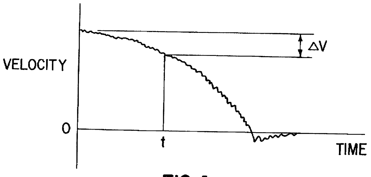
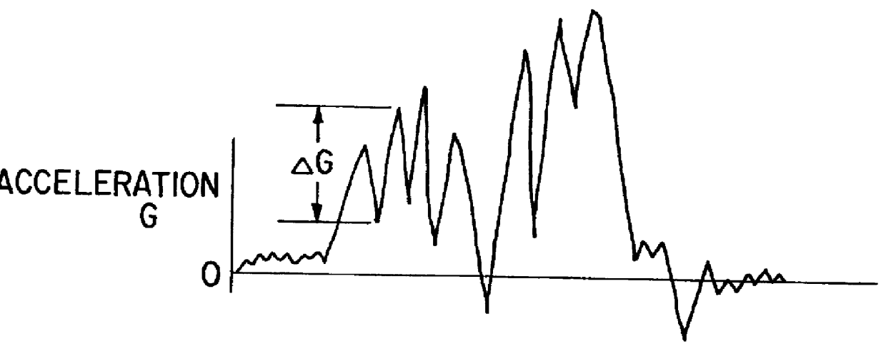
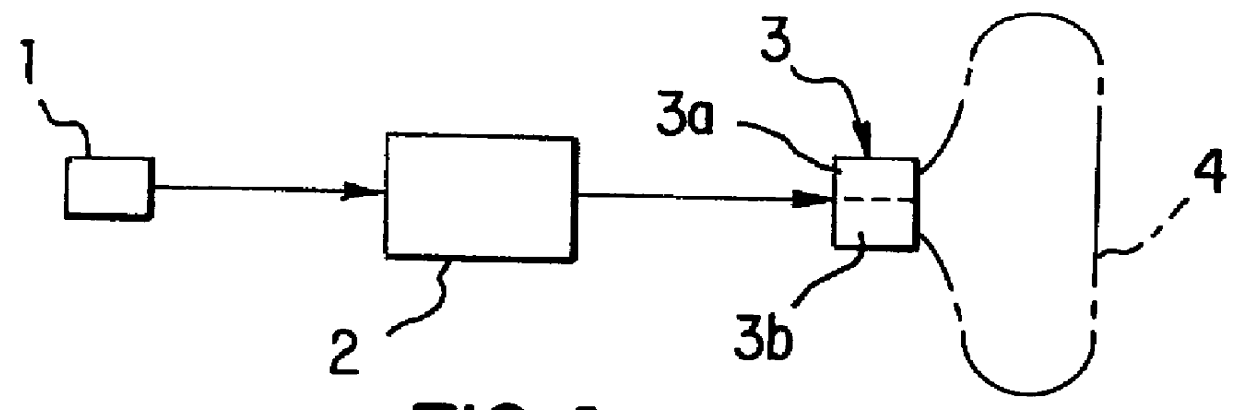
FIG. 1a is a block diagram of an occupant protective device according to an embodiment, FIGS. 1b and 1c are graphs showing wave forms of acceleration and velocity.

The occupant protective device comprises one acceleration sensor 1, a control circuit 2 into which an acceleration signal output from the acceleration sensor 1 is input, inflator means 3 actuated by the control circuit 2, and an air bag 4 inflated with gas from the inflator means 3. The air bag 4 may be either a driver air bag or a passenger air bag.

The inflator means 3 consist of two inflators, i.e. a first inflator 3a and a second inflator 3b. The inflator means 3 may consist of three inflators or more, or consist of one inflator which can control the amount of gas to be generated. When the inflator means 3 consist of a plurality of inflators, each inflator has capacity differing from each other and the sequence of ignition of the inflators each having different capacity is suitably selected, whereby the speed of deployi...


PUM


Abstract

An occupant protective device, which can precisely determine clash severity of a vehicle collision and suitably protect an occupant according to the clash severity, detects acceleration by an acceleration sensor 1, finds the acceleration, the magnitude of the acceleration, the variation with time of the acceleration, and the decrease in velocity in a control circuit 2, determines clash severity, and actuates inflators 3a, 3b according to the clash severity.

Description

The present invention relates to an occupant protective device for protecting an occupant in a collision and, more particularly, to an occupant protective device for protecting an occupant with an air bag device. In detail, the present invention relates to an occupant protective device in which the amount of gas for deploying an air bag is controlled corresponding to the severity of a vehicle collision.DESCRIPTION OF PRIOR ARTU.S. Pat. No. 4,243,248 to Scholtz et al discloses an air bag device having two inflators which are actuated in a collision with time delay to inflate an air bag in two stages, whereby the ear drums of an occupant can be protected from rapid increase in the inner pressure of cabin.FIG. 4 is a schematic diagram of the air bag device of U.S. Pat. '248. The air bag device includes clash severity detecting means 7, 8 having two acceleration detectors B.sub.1, B.sub.2 and determination units S.sub.1, S.sub.2. Threshold values S.sub.1, S.sub.2 (S.sub.1 <S.sub.2) a...

Claims


Application Information

Patent Timeline
IPC IPC(8): B60R21/01B60R21/16B60R21/0132B60R21/015
CPCB60R21/01558B60R21/0132B60R2021/01225
Inventor YOSHIDA, RYOICHI
Owner JOYSON SAFETY SYST JAPAN KK
Why Eureka
Try Eureka