Apparatus for measuring characteristics of optical fiber

a technology of optical fiber and optical fiber, applied in the direction of optical apparatus testing, reflectometers detecting back-scattered light in the frequency domain, instruments, etc., can solve the problem of difficult to set the relative frequency difference .vertline.f1-f2 vertline accurately, and the accuracy of the detection of the returned light 6a is adversely affected

Inactive Publication Date: 2000-04-25
YOKOGAWA ELECTRIC CORP
View PDF8 Cites 20 Cited by
  • Summary
  • Abstract
  • Description
  • Claims
  • Application Information

AI Technical Summary

Problems solved by technology

For this purpose, according to the related technique, the frequency of each of the light sources 3 and 13 is controlled to determine the relative frequency difference .vertline.f1-f2.vertline.. However, it is not easy to set the relative frequency difference .vertline.f

Method used


Image

  • Apparatus for measuring characteristics of optical fiber
  • Apparatus for measuring characteristics of optical fiber

Examples


Embodiment Construction

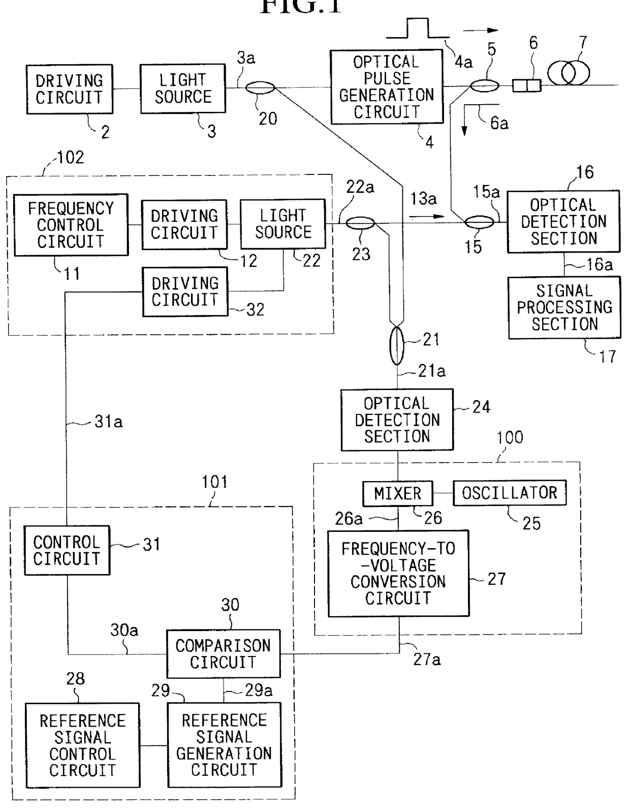
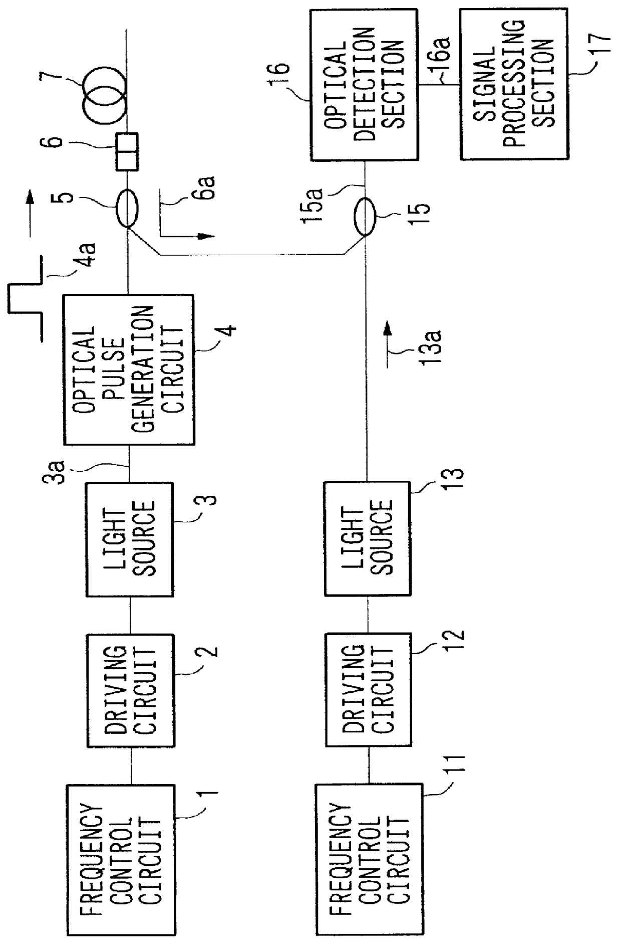
FIG. 1 is a block diagram showing a configuration of an apparatus for measuring the characteristics of an optical fiber according to an embodiment of the present invention. Elements in FIG. 1 which are the same as those in FIG. 2 are indicated by like reference numbers and will not be described here. An optical directional coupler 20 is provided between the light source 3 and the optical pulse generation circuit 4 to branch the coherent light 3a toward the optical pulse generation circuit 4 and an optical directional coupler 21. A light source 22 has a function equivalent to that of the light source 13 (FIG. 2) and is different from the light source 13 only in that it is driven by the driving circuit 12 and a driving circuit 32 (to be described later). The optical directional coupler 23 is provided between the light source 22 and the optical directional coupler 15 to branch coherent light 22a toward the optical directional coupler 15 and the optical directional coupler 21. The optic...


PUM


Abstract

There is provided an apparatus for measuring the characteristics of an optical fiber in which a frequency difference between first and second coherent light respectively generated by first and second light sources can be accurately set and wherein preferable coherent detection can be carried out in accordance with frequency components of returned light. First coherent light at a frequency f1 is converted into a pulse light which is output to the optical fiber to be measured. The characteristics of the optical fiber are measured by multiplexing returned light from the optical fiber to be measured and second coherent light at a frequency f2 and by detecting the multiplexed light. A component |f1-f2| is detected from an optical signal obtained by the multiplexed light and is mixed with a signal at a frequency fr to decrease the frequency. An electric signal at a voltage level corresponding to a differential frequency |f1-f2|-fr included in the mixed signal is generated, and a predetermined voltage level is generated which corresponds to a set value for an optical frequency difference between the first and second coherent light. The second light source is driven based on the difference between the two voltage levels to correct the frequency of the second coherent light.

Description

1. Field of the InventionThe present invention relates to an apparatus for measuring various characteristics of an optical fiber. More particularly, the present invention relates to an apparatus for measuring the characteristics of an optical fiber by inputting an optical pulse to the optical fiber, by multiplexing returned light from the optical fiber and locally oscillated light and by performing heterodyne detection.This application is based on Japanese patent application No. Hei 9-174767 the contents of which are incorporated herein by reference.2. Description of Related ArtFIG. 2 shows a configuration of an apparatus for measuring the characteristics of an optical fiber according to a related technique. A frequency control circuit 1 controls a driving circuit 2 to stabilize the frequency (frequency f1) of coherent light 3a generated by a light source 3. When an optical pulse generation circuit 4 converts the coherent light 3a into pulse light 4a, the pulse light 4a sequentially...

Claims


Application Information

Patent Timeline
IPC IPC(8): G01M11/00G01M11/02G02B6/00
CPCG01M11/3172
Inventor UCHIYAMA, HARUYOSHILEE, ZHIXIEN
Owner YOKOGAWA ELECTRIC CORP
Why Eureka
Try Eureka