Punched plate material carrying-out system

a carrying-out system and material technology, applied in the direction of manufacturing tools, metal-working feeding devices, stacking articles, etc., can solve the problems of excessive system size, increased vacuum pads, and high manufacturing cost of the carrying-out system of punched plate material, so as to simplify the carrying-out system and reduce the total size and total manufacturing cost of the system. , the effect of reducing the number of vacuum pads

Inactive Publication Date: 2000-05-02
U S AMADA
View PDF20 Cites 41 Cited by
  • Summary
  • Abstract
  • Description
  • Claims
  • Application Information

AI Technical Summary

Benefits of technology

to provide a punched plate material carrying-out system, which can reduce the number of vacuum pads to simplify the punched plate material carrying-out system and thereby to reduce the total size and the total manufacturing cost of the system.

Problems solved by technology

In the conventional punched plate material carrying-out system as described above, however, since a great number of vacuum pads are arranged in both X- and Y-axis directions roughly at regular intervals on the lift frame so that the punched product of the maximum size can be sucked, that is, in order to suck all over the surfaces of various products of different sizes, there exists a problem in that the number of vacuum pads increases.
As a result, the mechanism of the punched plate material carrying-out system is complicated with increasing number of vacuum pads, thus causing a problem in that the manufacturing cost of the punched plate material carrying-out system is relatively high.
In addition, since the sizes of the slider, the guide members, etc. increase with increasing number of the vacuum pads, another problem arises in that the system size is excessively large.

Method used


Image

  • Punched plate material carrying-out system
  • Punched plate material carrying-out system
  • Punched plate material carrying-out system

Examples


Embodiment Construction

The punched plate material carrying-out system according to the present invention will be explained hereinbelow, by taking the case where a plate material (work) is punched out to a punched plate material (referred to as a punched product) by a punch press machine. However, a plate material can be punched off by user of a laser processing machine.

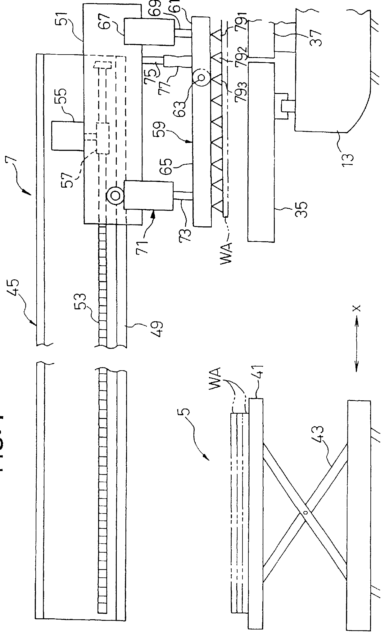
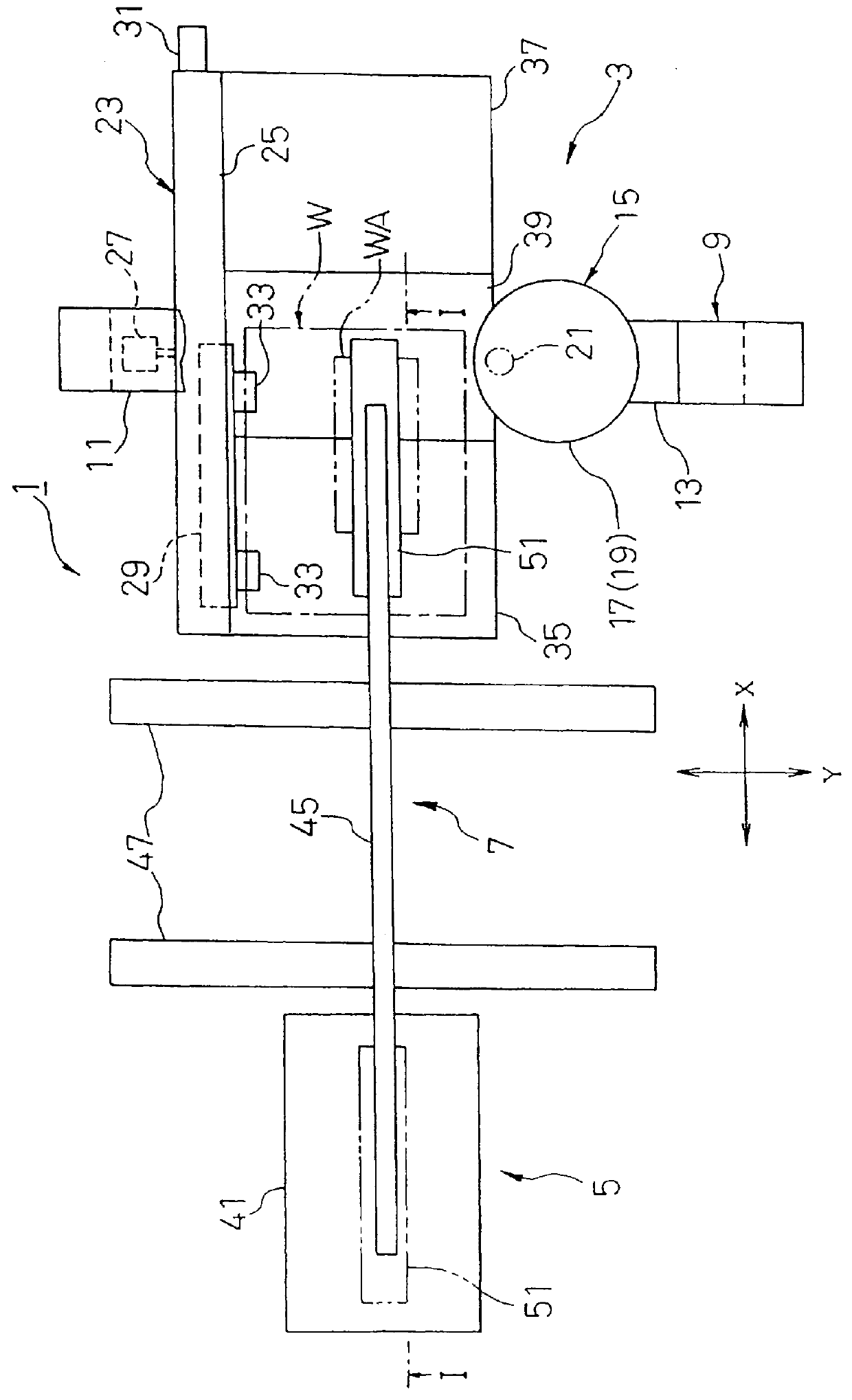
With reference to FIGS. 1 and 2, the punched plate material carrying-out system according to the present invention is roughly composed of a punch press machine 3 for punching a plate material (work) W into a punched product WA, a product support unit 5 arranged in the vicinity (on the left side in FIGS. 1 and 2) of the punch press machine 3, and a product carry-out unit 7 interposed between the punch press machine 3 and the product support unit 5. The product support unit 5 can support a plurality of punched products WA, and the product carry-out unit 7 can take out the punched product WA from the punch press machine 3 and further carries a...


PUM

PropertyMeasurementUnit
gravity centeraaaaaaaaaa
shapeaaaaaaaaaa
gravityaaaaaaaaaa

Abstract

A slider of the punch carry out unit is moved in the X-axis direction adjacent a punching section of the punch press machine before or after a plate material is punched into a punched product by a punch press machine. At the same time, a gravity center and a shape of the punched product are calculated and recognized on the basis of the manufacturing data. On the basis of the obtained gravity center and the shape of the punched product, the gravity center of the punched product is moved under the lift arm by the X- and Y-axis locating mechanism. Vacuum pads located just over the punched product are selected or discriminated. Then, the lift arm is lowered and the punched product is held by actuating only the discriminated vacuum pads. During this lift motion, it is preferable to bend one end of the punched product slightly upward to easily separate the punched product from the remaining flat plate material. After the punched product has been lifted, the punched product is moved horizontally away from the punch press, and is then lowered on the punched product supporting unit by releasing only the actuated vacuum pads. Since only the vicinity of the gravity center of the punched product is held by a minimum possible number of the vacuum pads, irrespective of the size and shape of the punched products, the number of the vacuum pads can be reduced.

Description

1. Field of the InventionThe present invention relates to a punched plate material carrying-out system, and more specifically to a system for carrying out a plate material punched by a processing machine (e.g., a punch press machine, laser processing machine, etc.) onto a punched product supporting unit (e.g., table).2. Description of the Prior ArtA conventional punched plate material carrying-out system will be first explained hereinbelow. The system is provided with a punch press machine (as an example of the hole-forming machines). The punch press machine has a punching section for punching at least one punch hole at any desired portion in a plate material (work) to manufacture a punched product, and a plate material locating mechanism for locating the plate material at a correct punching position.Further, after the plate material has been punched out as a punched product, the punched plated material (i.e., punched product) must be carried out from the punch press machine to the ...

Claims


Application Information

Patent Timeline
Patent Type & Authority Patents(United States)
IPC IPC(8): B21D43/20B21D43/18B65G47/91B65G57/04B65G57/03B65G57/02B21D28/26B21D45/04
CPCB21D43/18B21D43/20B65G57/04B65G57/035B65G47/918Y10T83/0453Y10T83/0476Y10T83/0524Y10T83/145Y10T83/162Y10T83/18Y10T83/2037Y10T83/2057Y10T83/207Y10T83/2185Y10T83/222
Inventor KANAZAWA, MASATO
Owner U S AMADA
Why Eureka
Try Eureka