Projection display device

a projection display and display device technology, applied in the field of projection display devices, can solve problems such as breakage, breakage at the edge, corner or the like of the light valve, and the operation of each element by mistak

Inactive Publication Date: 2000-05-02
SEIKO EPSON CORP
View PDF79 Cites 85 Cited by
  • Summary
  • Abstract
  • Description
  • Claims
  • Application Information

AI Technical Summary

Benefits of technology

In order to solve the above-mentioned problems, in the present invention, a projection display device which separates light from a light source into a plurality of color lights, modulates each color light through a light valve in response to image information, and recombines the modulated lights of each color with an optical combining means comprising a prism body to enlarge and project an image onto a screen through a projection means, wherein the structures are used such that the periphery of the light valve is protected to prevent the invasion of external light, breakage and the like, and the light valve is detachably fixed on the prism body.
Accordingly, since the light valve frame plate protects the periphery of the light valve, the light valve will not break when fixing it onto the prism body or the like. Further, in a state where the light valve is built in the projection display device, because the periphery is covered by a light valve frame plate, there is no possibility that there may be an operation by mistake because of the entrance of the external light.
Furthermore, when some defects occur in the light valve as time passes by and the light valve changes, the light valve frame plate which holds the light valve can be detached from the fixing frame plate, which is bonded and fixed to the prism body, and it is good to fix the light valve frame plate which holds the new light valve to the fixing frame plate. Thus, since the light valve is not directly bonded and fixed to the prism body, the light valve can be easily replaced without damage to the front surface of the prism body.
When the fixing frame plate and the light valve frame plate have specified ranges of linear expansion coefficients compared to that of the prism body, distortion of these members by thermal expansion will not adversely affect focusing adjustment and alignment adjustment. Furthermore, if the prism body, fixing frame plate, and light valve frame plate define the linear expansion coefficient as E1, E2, and E3, respectively, it is most preferable that the linear expansion coefficient E1, E2, and E3 is the same, but at least, it is preferable that the relationship of E1<E2<E3 is established. By having a linear expansion coefficient, which is larger than that of the prism body and smaller than that of the light valve frame plate, the linear expansion coefficient of the fixing frame plate is positioned between the prism body composed of optical glass having a small linear expansion coefficient and the light valve frame plate formed by a material generally having a larger linear expansion coefficient, the effect of thermal distortion caused by the difference in linear expansion coefficient among the three things can be moderated.
The light valve frame plate has a first frame plate and a second frame plate, and can use the structure which can hold in a state where the light valve is inserted between these frame plates.
A liquid crystal device can be used as the light valve. The present invention is particularly effective for a liquid crystal device which has inferior electrostatic resistance and can easily cause an erroneous operation due to the invasion of external light.

Problems solved by technology

However, when the light valve is directly bonded and fixed to the light incident surface of the prism body, it involves the following problems to be solved.
First, external light which enters from the external part of the device enters the light valve, there may be a possibility that each element may be operated by mistake.
Moreover, direct handling of the light valve may cause its breakage, and this is not desirable.
For example, direct chucking of the light valve, for bonding the light valve by a jig to the prism body may cause breakage at the edge, corner or the like of the light valve.
Further, because the light valve is easily affected by static electricity, direct contact of the light valve for bonding it to the prism body is not desired.
In the light valve bonded to the prism body, part of the pixels may develop defects or the like as time passes by and the light valve changes.
However, it is difficult to exchange the light valve with defects with a new one since it is bonded and fixed to the prism body.
It is not easy to detach the bonded and fixed light valve without damaging the light incident face of the prism body.
Because of this, there are cases, for example, when exchanging the light valve with defects including the prism body, and this is not economical.
Furthermore, when the light valve is directly bonded and fixed to the prism body, the linear expansion coefficient of the light valve and the prism body are different so that thermal distortion may occur.

Method used


Image

  • Projection display device
  • Projection display device
  • Projection display device

Examples


Embodiment Construction

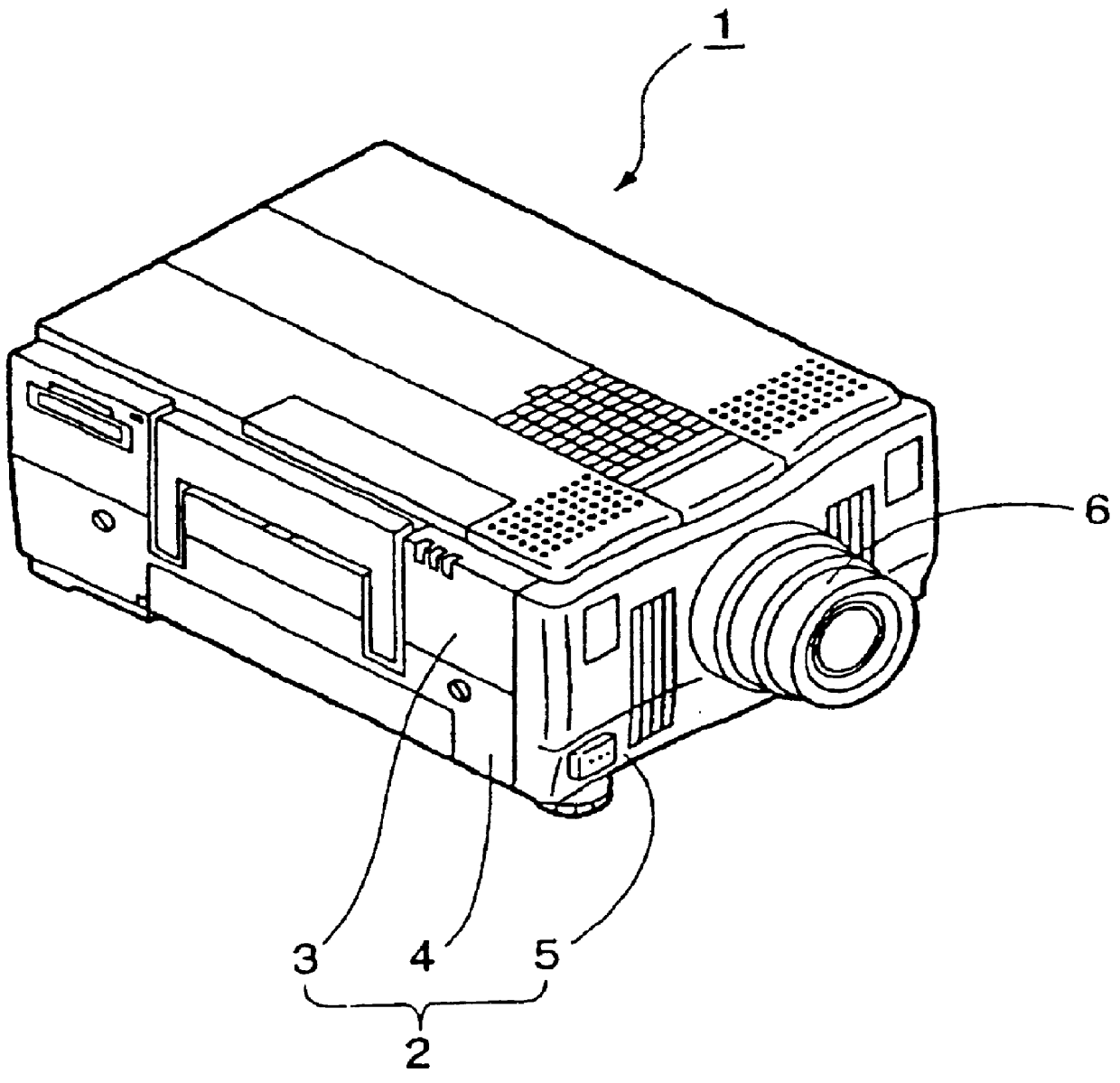
FIG. 1 shows the appearance of a projection display device in accordance with the present invention. The projection display device 1 of this example has an exterior case 2 which has a rectangular parallelepiped formation. The casing 2 is basically structured by an upper case 3, a lower case 4, and a front case 5, which defines the front face of the device. The top of a projection lens unit 6 protrudes from the central portion of the front case 5.

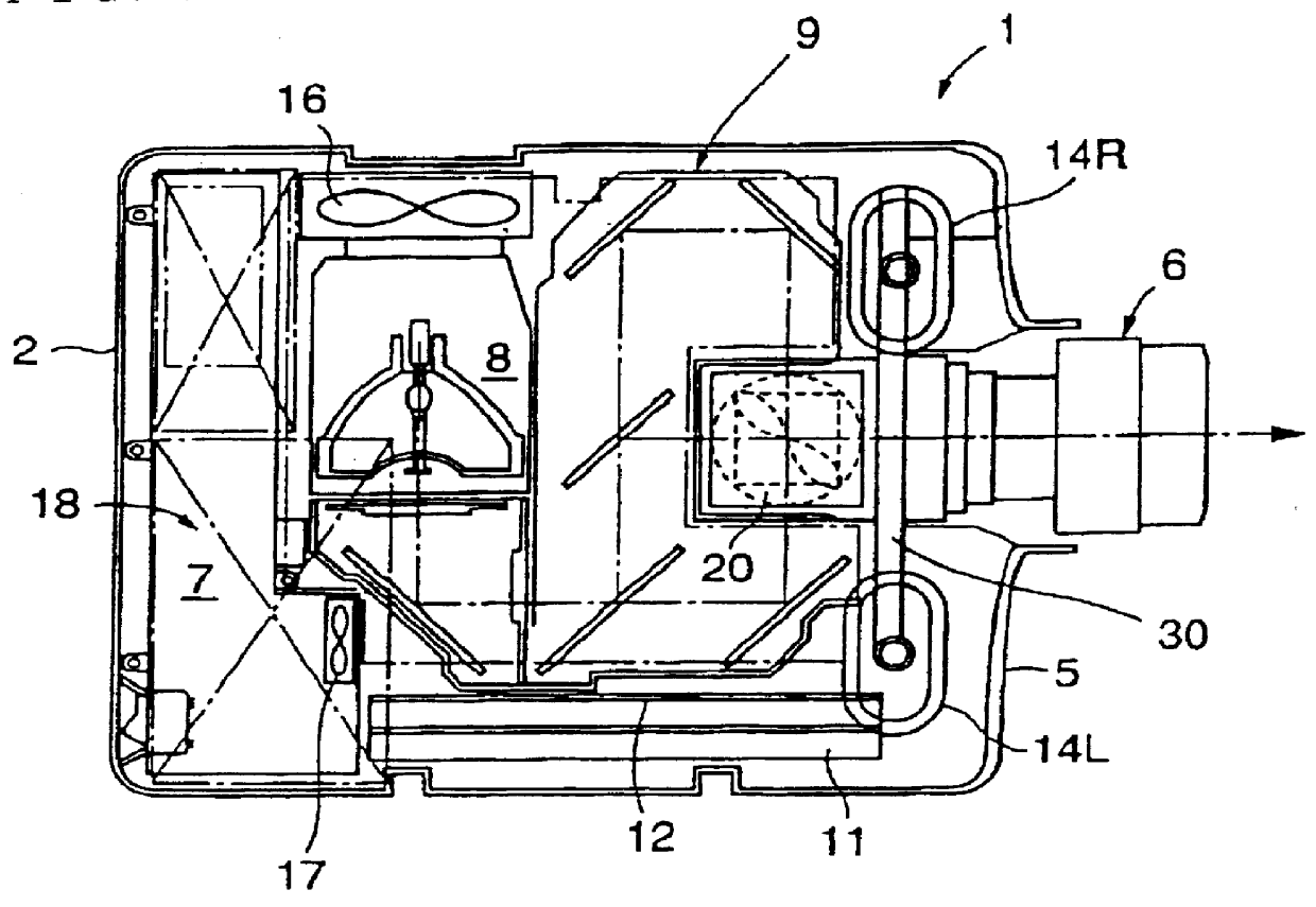
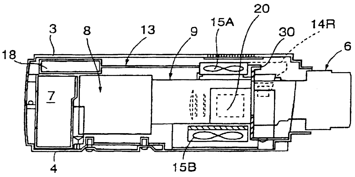
FIG. 2 shows the arrangement of each structural part in the internal part of the exterior case 2 of the projection display device 1. As shown in this figure, power source unit 7 is arranged in the rear edge side of the internal part of the exterior case 2. A light source lamp unit 8 and an optical lens unit 9 are placed in a position more adjacent to the front side of the device. The base edge side of the projection lens unit 6 is positioned in the center of the front side of the optical lens unit 9. Meanwhile, in another side of the optical...


PUM


Abstract

PCT No. PCT / JP97 / 04652 Sec. 371 Date Aug. 12, 1998 Sec. 102(e) Date Aug. 12, 1998 PCT Filed Dec. 17, 1997 PCT Pub. No. WO98 / 27453 PCT Pub. Date Jun. 25, 1998A liquid crystal panel unit is provided on the light incident face of a prism combining body. The unit has a light valve frame plate for holding a liquid crystal panel and a fixing frame plate fixed onto the light incident face with an adhesive layer. The light valve frame plate is screwed onto the fixing frame plate with a medial frame therebetween. By using wedge members, by adjusting the position of the light valve frame plate on the light incident face, it is possible to precisely position and fix the liquid crystal panel which is held there so that it is possible to control the shifted amount of the pixel alignment and precisely adjust the focus. Thus, it is possible to easily improve the accuracy. Furthermore, the fixing frame plate and the light valve frame plate are composed of materials having linear expansion coefficients ranging from +E,fra 1 / 4+EE to four times that of the prism combining body and from +E,fra 1 / 5+EE to five times that of the fixing frame plate, respectively.

Description

1. Field of the InventionThe present invention relates to a projection display device, which separates white light from a light source into three-color lights of red, blue and green, modulates these color lights through a light valve composed of a liquid crystal panel or the like in response to image information, and recombines the modulated lights with an optical combining means to enlarge and project an image onto a projecting surface through a projection means.2. Description of Related ArtA mechanism for fixing a light valve onto a prism body which is an optical combining means for a projection display device is disclosed in Japanese Patent Laid-Open Publication No. Hei 6-118368. In this fixing mechanism, the light valve is directly fixed onto the light incident face of the prism body with an adhesive.The use of such a mechanism permits the omission of a pixel alignment mechanism between a plurality of light valves, which modulate the light which is particularly separated into re...

Claims


Application Information

Patent Timeline
Patent Type & Authority Patents(United States)
IPC IPC(8): G03B21/00H04N9/31H04N5/74G02B27/14G03B21/14
CPCG02B27/1046G02B27/1073G02B27/145G02B27/149H04N9/3197G03B21/14H04N9/3105H04N9/317G03B21/00H04N5/7441G03B21/006G03B21/208G03B21/145
Inventor IINUMA, KAZUYUKIFUJIMORI, MOTOYUKISHINOHARA, KAZUTOKITABAYASHI, MASASHI
Owner SEIKO EPSON CORP
Why Eureka
Try Eureka