Device for adjusting ink supply gap for ink fountain apparatus

Inactive Publication Date: 2000-05-16
TOKYO KIKAI SEISAKUCHI LTD
View PDF4 Cites 19 Cited by
  • Summary
  • Abstract
  • Description
  • Claims
  • Application Information

AI Technical Summary

Problems solved by technology

The above-described conventional gap adjustment devices involve drawbacks.
Thus, a large number of parts are used, and the mechanism of the device is complex.
As a result, the frequency of failure is high, and maintenance and inspection are time consuming.
Accuracy in adjusting the gap between the ink foun

Method used


Image

  • Device for adjusting ink supply gap for ink fountain apparatus
  • Device for adjusting ink supply gap for ink fountain apparatus
  • Device for adjusting ink supply gap for ink fountain apparatus

Examples


Embodiment Construction

A device for adjusting an ink supply gap for an ink fountain apparatus according to an embodiment of the present invention will now be described with reference to the accompanying drawings.

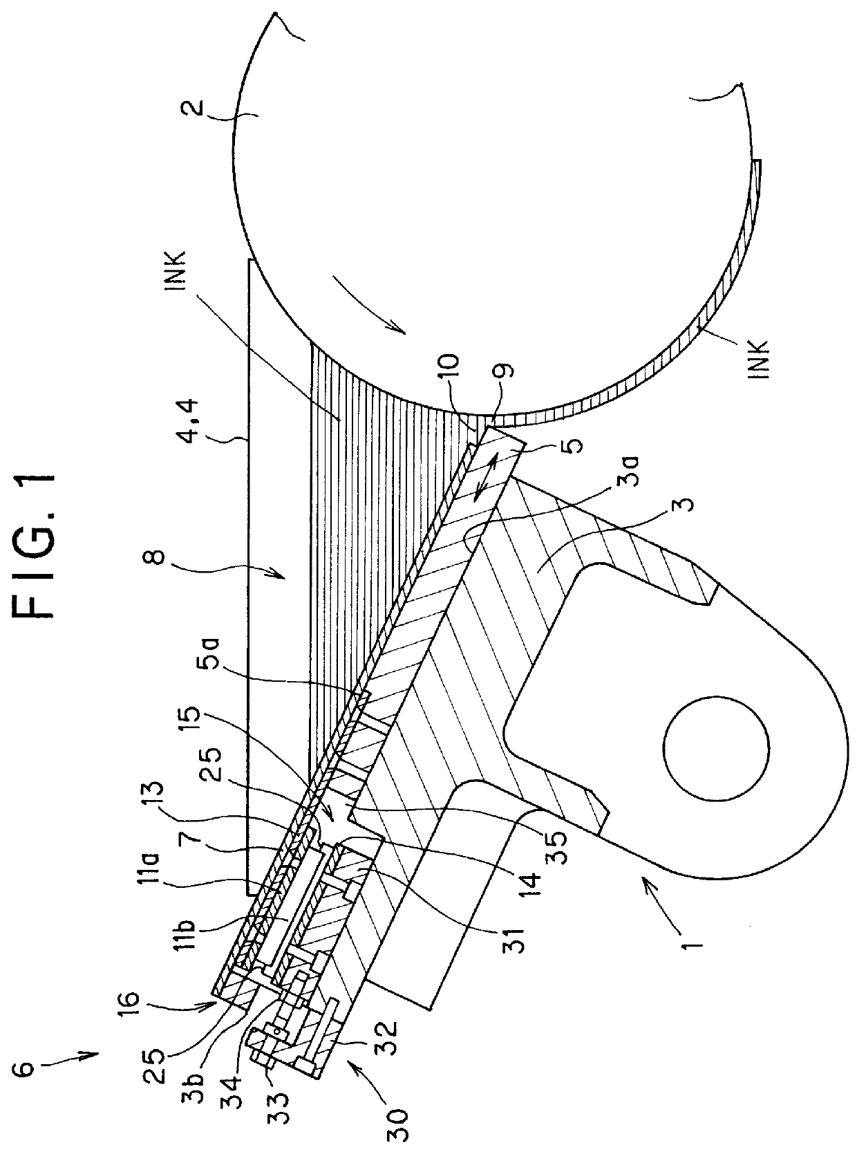
An ink fountain apparatus 1 shown in FIG. 1 is provided with a base 3 which faces an ink fountain roller 2 rotated by an unillustrated drive mechanism in the direction indicated by the arrow (in the counterclockwise direction). The front half of the base 3 has an upper surface which is stepped upward from the upper surface of the rear half of the base 3 and which forms a sloping surface 3a extending downward toward the ink fountain roller 2. The device for adjusting an ink supply gap is provided at the rear half of the base 3.

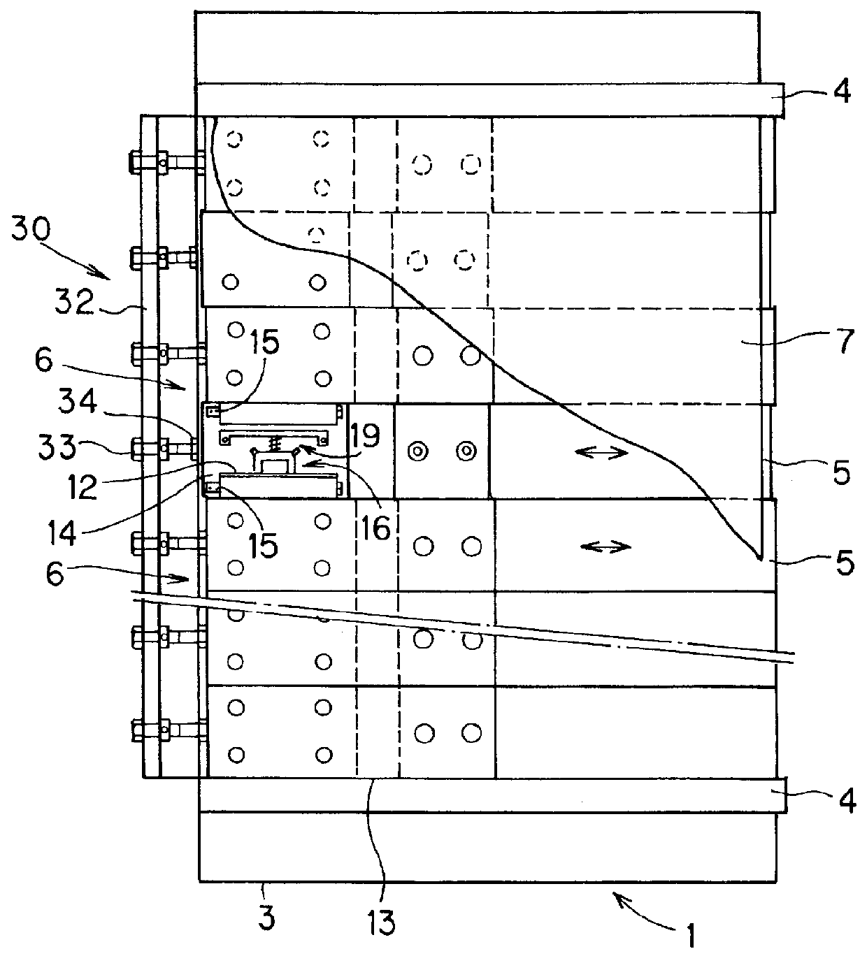
As shown in FIGS. 1 and 2, at both lateral ends of the base 3, a pair of side plates 4 are provided. The side plates 4 have arcuate forward edges which contact the peripheral surface of the ink fountain roller 2. A bottom plate 7 is provided between the side plates and in par...


PUM


Abstract

A device for adjusting an ink supply gap is employed in an ink fountain apparatus in which the bottom portion of the ink fountain apparatus forms a space for storing ink in cooperation with a peripheral surface of an ink fountain roller while a forward edge of the bottom portion faces the peripheral surface of the ink fountain roller in order to form a gap serving as an ink supply port. The device for adjusting an ink supply gap includes a plurality of blade segments and a plurality of ultrasonic linear motors corresponding to the blade segments. The blade segments are disposed on a base in a row extending in the axial direction of the ink fountain roller and are adapted to individually advance toward or retract from the ink fountain roller so as to adjust the opening of the ink supply port. The ultrasonic linear motors are adapted to individually advance or retract the corresponding blade segments.

Description

1. Field of the InventionThe present invention relates to a device for adjusting an ink supply gap for an ink fountain apparatus of a printing press, and more particularly to a device for adjusting an ink supply gap adapted to move blade segments toward or away from an ink fountain roller so as to adjust the width of the ink supply gap.2. Description of the Related ArtIn an ink fountain apparatus for an inking arrangement of a printing press, ink is stored in an elongated space of a substantially V-shaped cross section, which is formed by the peripheral surface of an ink fountain roller, the bottom portion of the ink fountain apparatus having its forward edge located in proximity to the peripheral surface of the ink fountain roller with an appropriate gap therebetween, and a pair of side plates, each disposed at one lateral end of the bottom portion. When the ink fountain roller is rotated, the ink stored in the elongated space is withdrawn through an ink supply port, i.e., a gap be...

Claims


Application Information

Patent Timeline
IPC IPC(8): B41F31/04
CPCB41F31/04
Inventor TOMITA, YUKOTAIRA, SHINSUKE
Owner TOKYO KIKAI SEISAKUCHI LTD
Why Eureka
Try Eureka