This helps you quickly interpret patents by identifying the three key elements:
Problems solved by technology
Method used
Benefits of technology
Benefits of technology
In accordance with the present invention, since the optical fiber is not fixed within its fiber-positioning hole disposed on the front end face side of the ferrule, the optical fiber is longitudinally compressible. The tip end position of the optical fiber can be fine adjusted with compression. Namely, by compressing the optical fibers during PC connection, PC connection can be securely established without generating optical transmission loss due to bad connection. Also, upon the longitudinal compression, an optical fiber-positioning hole functions as a guide for compressing the optical fiber in the longitudinal direction. As a consequence, neither flexing nor buckling would occur, and the optical fiber is prevented from breaking.
In accordance with the present invention, since the optical fibers are arranged such that their fluctuations in tip face positions are within an allowable extent with respect to the permissible amount of compression of the optical fibers determined by the lengths of their corresponding fiber-positioning holes, these fluctuations in the tip face positions can be absorbed by longitudinally compressing the optical fibers. Namely, by compressing the optical fibers upon PC connection, their tip face positions align with each other, whereby PC connection can be securely established in an optical connector having a plurality of optical fibers as well, without any fear of generating optical transmission loss.
By pressing the optical fiber against a wall face of the optical-fiber-aligning groove with an optical-fiber-pressing member, the optical fiber can be easily and securely fixed to the ferrule.
When the optical fibers are pre-compressed such that their tip positions align with each other, their amount of fluctuation in tip face position can further be reduced. In the case where the aligning groove portion is provided, when the optical fiber is made longitudinally compressible within the aligning groove portion as well, the amount of fluctuation can further be adjusted. In particular, using the C-shaped aligning groove is preferable since there is no fear of the optical fiber flexing. Providing the aligning groove portion is also advantageous in that the length of the fiber-positioning hole can be reduced.
A pressing member for pressing the periphery of the optical fibers may be disposed behind the fiber-positioning holes. More preferably, this pressing member also functions as the pressing member mentioned above. This case is advantageous in that it becomes further easier to securely fix the optical fibers to ferrule after compression.
Problems solved by technology
In a multicore optical connector, secure PC connection cannot be established when tip faces of optical fibers become irregular.
Method used
Image
Click on the blue label to locate the original text in one second.
Reading with bidirectional positioning of images and text.
Examples
first embodiment
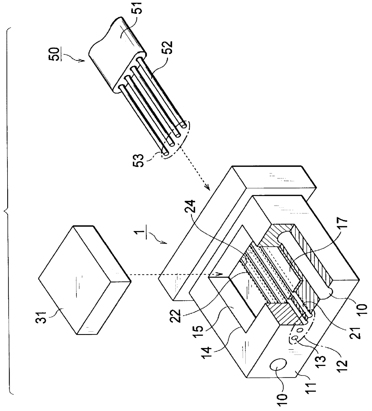
FIG. 1 is an exploded perspective view of the optical connector in accordance with the present invention,
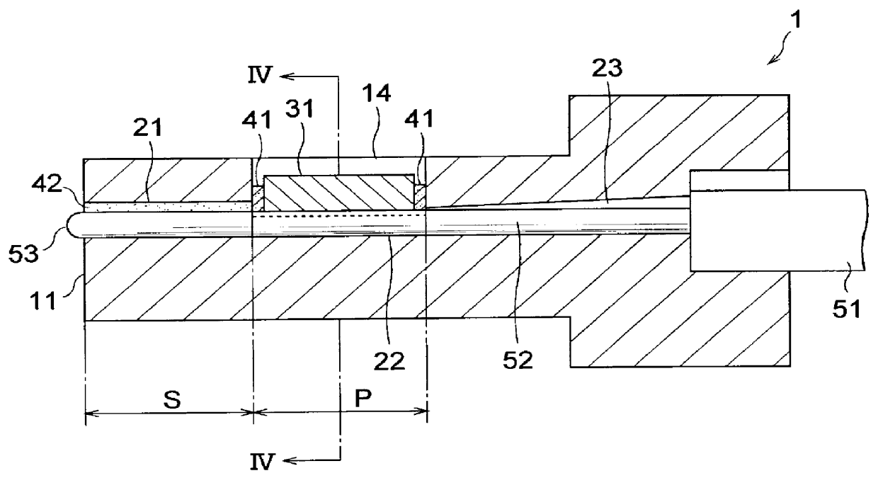
FIG. 2 is a vertical sectional view thereof,
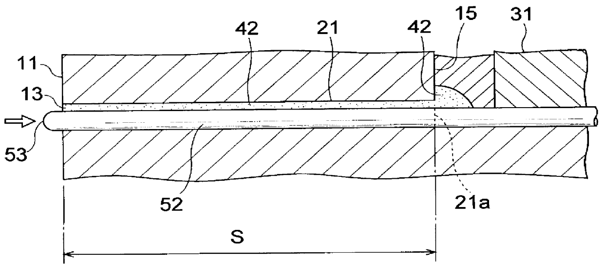
FIG. 3 is an enlarged view thereof near its front end face portion, and
FIG. 4 is a transverse sectional view thereof;
FIG. 5 is an enlarged view of an aligning groove portion in FIG. 4;
FIGS. 6 to 8 are views showing an optical fiber compressing step for the optical connector of FIG. 1;
FIG. 9 is a view showing a state where an optical fiber in an aligning groove of the optical connector of FIG. 1 is compressed with no pressing member, whereas
FIG. 10 is a view showing a state where it is compressed with a pressing member;
second embodiment
FIG. 11 is an exploded perspective view showing the optical connector in accordance with the present invention,
FIG. 12 is a transverse sectional view thereof, and
FIG. 13 is a vertical sectional view thereof; and
third embodiment
FIG. 14 is an exploded perspective view showing the optical connector in accordance with the present invention, whereas
FIG. 15 is a vertical sectional view thereof.
In the following, preferred embodiments of the present invention will be explained in detail with reference to the accompanying drawings. For making it easier to understand the explanation, constituents identical to each other among the drawings will be referred to with numerals identical to each other whenever possible, without repeating their overlapping descriptions. Sizes and shapes in the drawings are sometimes exaggerated for convenience of explanation, and ratios in sizes of the individual parts do not always correspond to those in practice.
FIG. 1 is an exploded view showing a first embodiment of the optical connector in accordance with the present invention. This optical connector has a ferrule 1 for securing four (4-core) bare optical fibers 52 exposed by removing a coating 51 from a tip portion of a ribbon-shape...
PUM
Abstract
An optical connector in which an optical fiber is fixed within a ferrule such that a tip of the optical fiber is disposed at a front end face position of the ferrule. An optical-fiber-positioning hole formed so as to directly extend into the ferrule from an optical connecting orifice formed in the front end face of the ferrule has a diameter greater than a diameter of the optical fiber positioned within the optical-fiber-positioning hole, the optical-fiber-positioning hole having therein a compressible unfixing area for allowing the optical fiber to compress along the optical-fiber-positioning hole, and a fixing area, disposed behind the compressible unfixing area, for fixing the optical fiber to the ferrule.
Description
1. Field of the InventionThe present invention relates to an optical connector for connecting optical fibers to each other.2. Related Background ArtPhysical-Contact (PC) connection in which end faces of optical fibers are butted against and brought into contact with each other so as to form an optical link is employed in optical connectors. In a multicore optical connector, secure PC connection cannot be established when tip faces of optical fibers become irregular. Hence, there has been developed a technique for eliminating such irregularity and effecting secure PC connection.For example, known technique for PC connection is disclosed in Japanese Patent Application Laid-Open No. 9-159860 (hereinafter referred to as Conventional Example 1) and a technique for curing irregular tip faces is disclosed in Katagiri et al., "A Study on Quickly & Easily Assembling Techniques of Multifiber Connector," (Communications Society Conference of the Institute of Electronics and Information and Com...
Claims
Application Information
Patent Timeline
Application Date:The date an application was filed.
Publication Date:The date a patent or application was officially published.
First Publication Date:The earliest publication date of a patent with the same application number.
Issue Date:Publication date of the patent grant document.
PCT Entry Date:The Entry date of PCT National Phase.
Estimated Expiry Date:The statutory expiry date of a patent right according to the Patent Law, and it is the longest term of protection that the patent right can achieve without the termination of the patent right due to other reasons(Term extension factor has been taken into account ).
Invalid Date:Actual expiry date is based on effective date or publication date of legal transaction data of invalid patent.

