Reduction of wave making by multi-hull surface vessel

Inactive Publication Date: 2000-05-23
ORR ANTHONY HUGH
View PDF8 Cites 18 Cited by
  • Summary
  • Abstract
  • Description
  • Claims
  • Application Information

AI Technical Summary

Benefits of technology

According to the present invention there is provided a multi hulled vessel in which its two outer most hulls are parallel and double ended, where--in one hull has a bow that displaces water at least to the right of its fore and aft axis and is at least asymmetric in its aftward part when viewed in plan at the datum waterline; beneath the waterline and in schematic representation, that part of the hull aftward of the divergent bow comprises a right and left side surface and a bottom surface such that each surface is an aftward continuation of its respective bow and in particular that the right side surface and bottom surface continues aftwardly from t

Problems solved by technology

It is well known that hulls of this shape and in the light/medium displacement category experience a disproportionately large increase in drag if hi

Method used


Image

  • Reduction of wave making by multi-hull surface vessel
  • Reduction of wave making by multi-hull surface vessel
  • Reduction of wave making by multi-hull surface vessel

Examples


Embodiment Construction

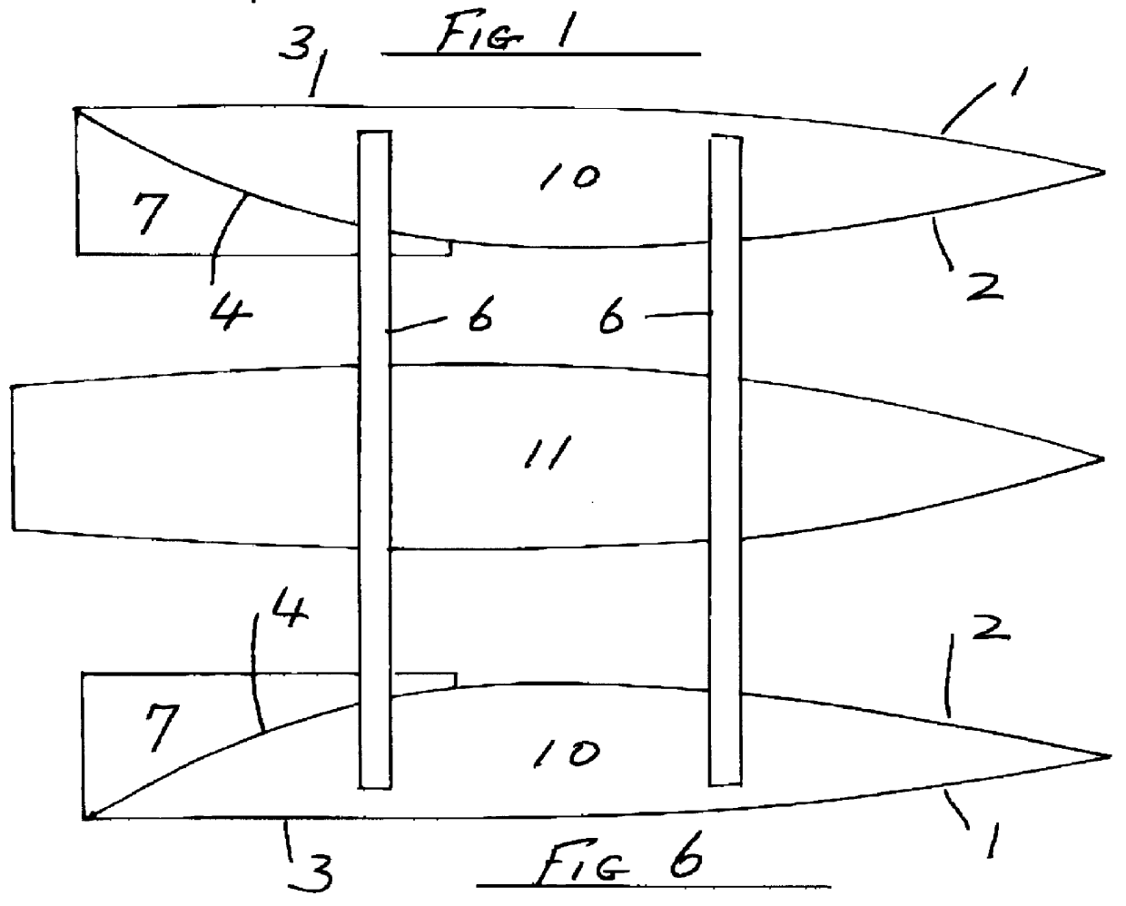
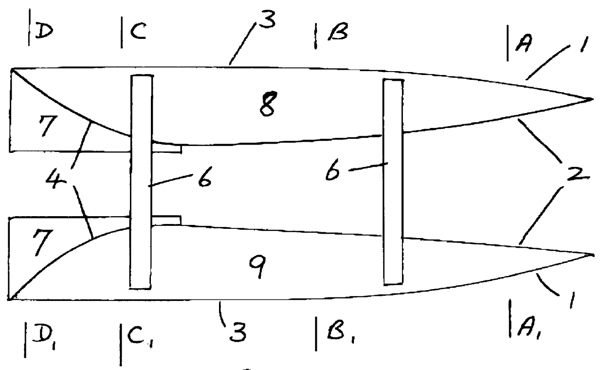
In operation the water particles displaced by the bow of each hull will follow streamlines that pass aftward along the hull. Along the hulls right side surface and its bottom surface these particle streamlines do not converge either inwardly to the fore and aft axis of the hull when viewed in plan, nor aftwardly upward in elevation. It is only along the aftwardly convergent left side surface of the hull that the particle streamlines converge aftwardly. This convergence of the water particles is between those particles passing along the hulls right side and bottom surface and those having passed along the hulls left side surface. At slow speed the particles have plenty of time in which to re-arrange their lateral position along the hull's aftwardly convergent left side surface. With increasing hull speed that time for re-arrangement decreases. This results in a reduction of the water flowing along the full length of the convergent stern surface. The inertia of water particles can onl...


PUM


Abstract

A multi hulled vessel in which its two outermost hulls are parallel and have a configuration such that one hull is a mirror image of the other and are double ended, each hull is characterized by its stern part; beneath the waterline in which there is a continuation to the stern of the hulls bottom and one side surface without aftward convergence to the waterline or the fore and the aft axis, and in which the hulls other side surface converges towards the two said surfaces.

Description

The invention relates to vessel's of catamaran, trimaran and the slender integrated catamaran form that employ hulls one on each side of the vessels centre line symmetrically arranged and that these hulls taper aftwardly in their underwater stern part. It is well known that hulls of this shape and in the light / medium displacement category experience a disproportionately large increase in drag if high speeds are attempted. This resulting from the maintenance of a continuous waterflow over the hull's stern part.A hull form that creates the condition for air to be introduced to the otherwise submerged tapering aft hull surface and thereby the cessation of the continuous flow of water is already known.In operation at sea this type experiences the re-establishment of continuous water flow and the obligatory increase in drag. This occurs when heeled, and rolling.SUMMARY OF INVENTIONAccording to the present invention there is provided a multi hulled vessel in which its two outer most hulls...

Claims


Application Information

Patent Timeline
IPC IPC(8): B63B1/08B63B1/12B63B1/00
CPCB63B1/08B63B1/121B63B2003/085
Inventor ORR, ANTHONY HUGH
Owner ORR ANTHONY HUGH
Why Eureka
Try Eureka