Glass antenna device for an automobile

a technology for antenna devices and automobiles, applied in the direction of antennas, antenna details, antennas, etc., can solve the problems of poor s/n ratio, insufficient receiving sensitivity, insufficient signal receiving sensitivity and directivity for fm broadcast,

Inactive Publication Date: 2000-06-06
ASAHI GLASS CO LTD
View PDF11 Cites 28 Cited by
  • Summary
  • Abstract
  • Description
  • Claims
  • Application Information

AI Technical Summary

Problems solved by technology

Further, the S/N ratio was poor because the parallel resonance frequency existed in a middle broadcast band, and the receiving sensitivity was insufficient because the resonance occurred in a single portion.
Further, when the defogger 90 was utilized as an antenna commonly used for a middle wave broadcast band and FM broadcast band and even when the shape of the defogger 90 was optimized for receiving middle wave broadcast signals, there were problems that the signal rec

Method used


Image

  • Glass antenna device for an automobile
  • Glass antenna device for an automobile
  • Glass antenna device for an automobile

Examples


example 1

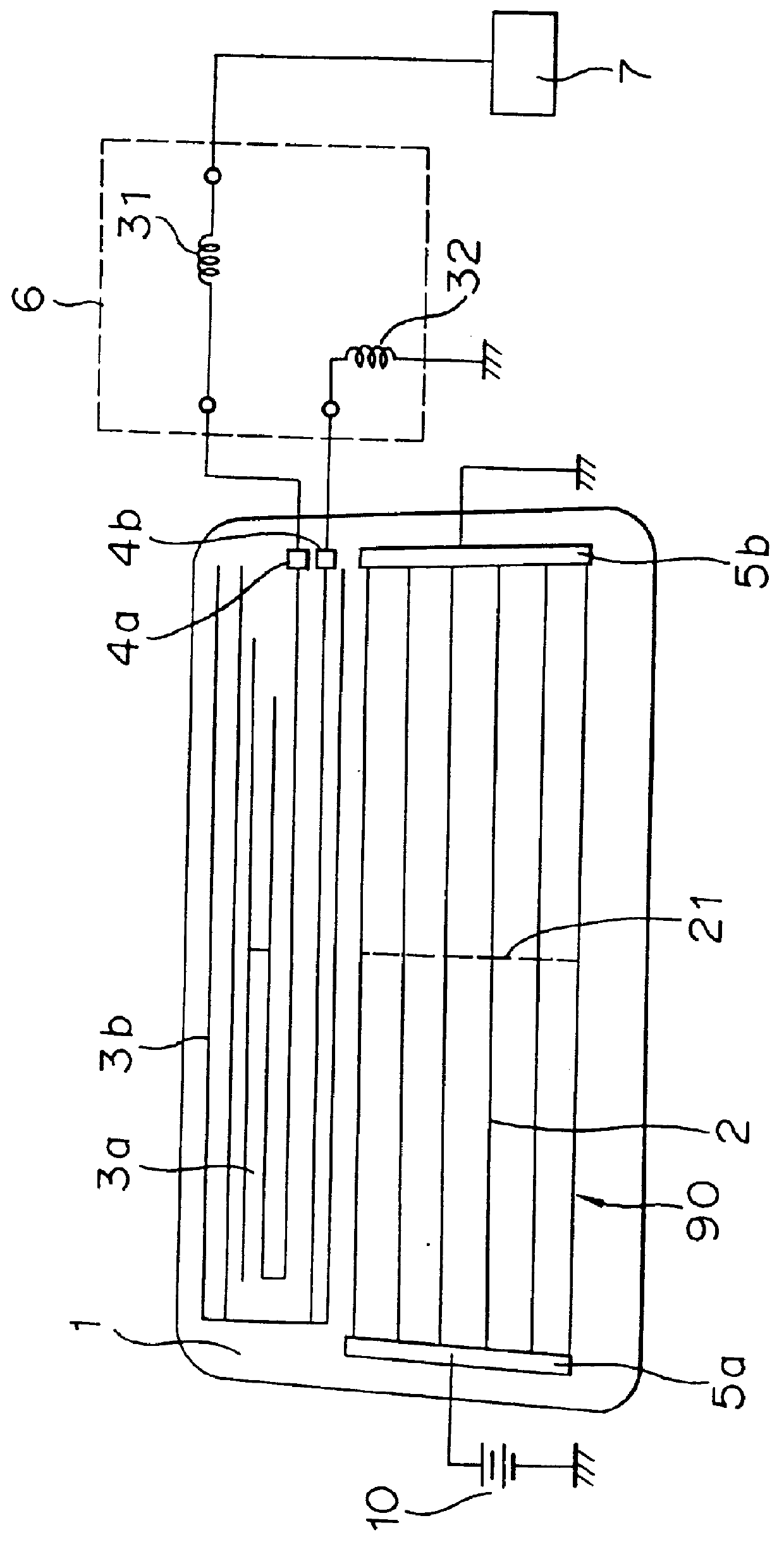
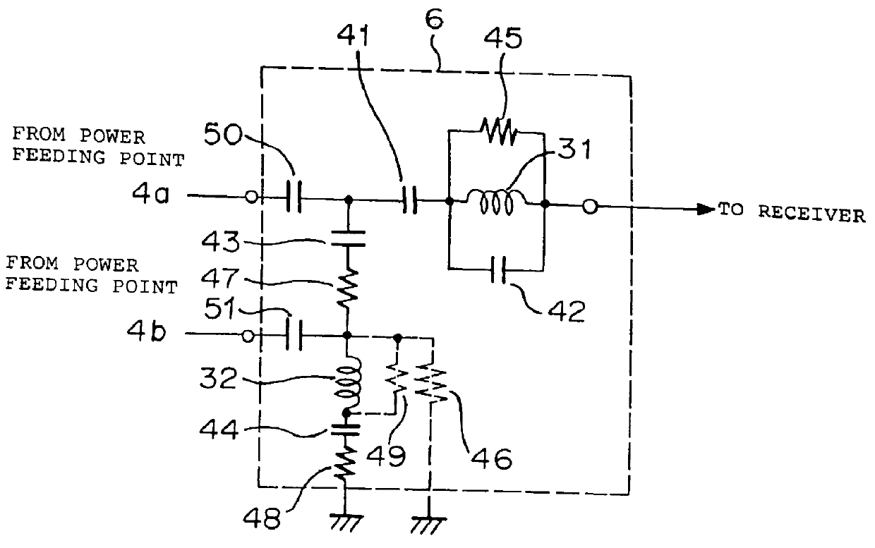
A rear window glass sheet for an automobile was used and a glass antenna device as shown in FIG. 1 was formed therein. For the resonance circuit 6, a circuit as shown in FIG. 3 was employed wherein the resistors 47, 48 and 49 and capacitors 50 and 51 were not provided (the resistors 47 and 48 and the capacitors 50 and 51 were shortcircuited, and the resistor 49 was opened). The circuit constants of the elements used were as follows.

First coil 31: 220 .mu.H

Second coil 32: 680 .mu.H

Capacitors 41, 44: 2200 pF

Bypass capacitor 42: 22 pF

Capacitor 43: 39 pF

Resistor 45: 10 k.OMEGA.

Resistor 46: 15 k.OMEGA.

The length and the shape of the first antenna conductor 3a were adjusted so as to obtain a preferable signal receiving performance in an FM broadcast band. The length of the second antenna conductor 3b was elongated as possible by maximizing the unable area so that signals in a middle wave broadcast band could be received preferably.

The distance between the upper portion or the lower portio...

example 3

The glass antenna device as shown in FIG. 1 was formed in a rear window glass sheet of automobile. The same resonance circuit 6 as in FIG. 6 was employed wherein the capacitors 50 and 51 and resistors 46, 48 and 49 were not provided (the resistors 46 and 49 were opened; the resistor 48 was shortcircuited and the capacitors 50 and 51 were shortcircuited). With respect to the elements used, the same circuit constants as in Example 1 were used except for the first coil 31, the coil 52 and the resistor 47. The circuit constants of these elements were as follows. In FIG. 11, a solid line shows a result of the measurement of the FM broadcast band sensitivity in Example 3.

First coil 31: 120.mu.H

High frequency choke coil 52: 2.7.mu.H

Resistor 47: 220.OMEGA.

example 4

The glass antenna device as shown in FIG. 1 was formed in the same manner as in Example 3 except that the high frequency choke coil was not provided. In FIG. 11, a dotted line shows a result of the measurement of the FM broadcast band sensitivity of Example 4.


PUM


Abstract

A first resonance is generated by the inductance of a first coil connected between a first antenna conductor in a window glass sheet and a receiver and the impedance of the antenna conductor, and a second resonance is generated by the inductance of a second coil connected between a second antenna conductor and an automobile body as the earth. The antenna conductor and the antenna conductor are in a capacitive coupling relation, whereby signals in different broadcast band: a low frequency band and a high frequency band, are well received.

Description

1. Field of the InventionThe present invention relates to a glass antenna device for an automobile suitable for received signals in a long wave broadcast band (LW band)(150-280 kHz), a middle wave broadcast band (530-1630 kHz), a short wave broadcast band (SW band)(2.3-26.1 MHz), an FM broadcast band (76-90 MHz, (Japan)), an FM broadcast band (88-108 MHz (U.S.A.)), a TV-VHF band (90-108 MHz and 170-222 MHz) and a TV-UHF band (470-770 MHZ), which has a high signal receiving sensitivity and a noise suppressing property and which is rich in productivity.2. Discussion of the BackgroundAs a glass antenna device for an automobile which is capable of improving the signal receiving sensitivity by utilizing resonance, there has been proposed a glass antenna device for an automobile as shown in FIG. 7 (JP-Y-4-53070).In this conventional example, a defogger 90 comprising heater strips 2 and bus bars 15a, 15b, 15c is provided in a rear window glass sheet 1 of an automobile, a choke coil 9 is co...

Claims


Application Information

Patent Timeline
IPC IPC(8): H01Q1/12H01Q1/32
CPCH01Q1/1271H01Q1/32
Inventor TERASHIMA, FUMITAKATABATA, KOHJIYAMAMOTO, TSUYOSHI
Owner ASAHI GLASS CO LTD
Why Eureka
Try Eureka