Image decoder and image memory overcoming various kinds of delaying factors caused by hardware specifications specific to image memory by improving storing system and reading-out system

a technology applied in the field of image decoding and image memory, can solve the problems of large increase in power consumption, significant delay in decoding process, and number of burst reads to be performed a number of times

Inactive Publication Date: 2000-06-13
GK BRIDGE 1
View PDF6 Cites 61 Cited by
  • Summary
  • Abstract
  • Description
  • Claims
  • Application Information

AI Technical Summary

Problems solved by technology

The three components composed of luminance components, blue chrominance components and red chrominance components are stored on separate pages, and since calculation needs to be performed for each of these pages, there is the problem that burst reads have to be performed a number of times which is proportionate to three times the number required to read the reference picture.
Since the number of executions of burst reads is increased as described above, the effect of this delay tRCD is also increased, so that a significant delay is caused within the decoding process.
This has a major drawback, however, in that there is a great increase in power consumption.
The activation of memory arrays requires an activation time of three clocks, so that the read of the reference picture will be unavoidably delayed by the time represented by these three clocks.
When images are divided and stored across a plurality of memory arrays, ther...

Method used


Image

  • Image decoder and image memory overcoming various kinds of delaying factors caused by hardware specifications specific to image memory by improving storing system and reading-out system
  • Image decoder and image memory overcoming various kinds of delaying factors caused by hardware specifications specific to image memory by improving storing system and reading-out system
  • Image decoder and image memory overcoming various kinds of delaying factors caused by hardware specifications specific to image memory by improving storing system and reading-out system

Examples


first embodiment

Section 1--Overall View of the Image Decoding Apparatus

FIG. 4A is a block diagram showing the entire construction of the image decoding apparatus in the first embodiment of the present invention. FIG. 6A, meanwhile, is a timing chart where the FIFO memory 4, the processor 5, the code encoder 6, and the image read / write unit 8 are arranged in the vertical axis and a time series for the processing of these components is shown in the horizontal axis. The following description will refer to FIG. 4A and FIG. 6A when referring to the overall construction of the image decoding apparatus.

As shown in FIG. 4A, the image decoding apparatus is composed of a stream input unit 1, a buffer memory 2, a memory module 3, a FIFO memory 4, a processor 5, a code encoder 6, a pixel calculation unit 7, an image read / write unit 8, a video output unit 9, a buffer 200, and a buffer 201.

The stream input unit 1 converts an MPEG data stream that has been serially inputted from outside into parallel data (herein...

second embodiment

In the second embodiment, the word length of the SDRAM in two bytes, so that when the luminance components, blue chrominance components, and red chrominance components are each 1 byte long, luminance components, blue chrominance components, and red chrominance components for two pixels can be stored in one word in the SDRAM.

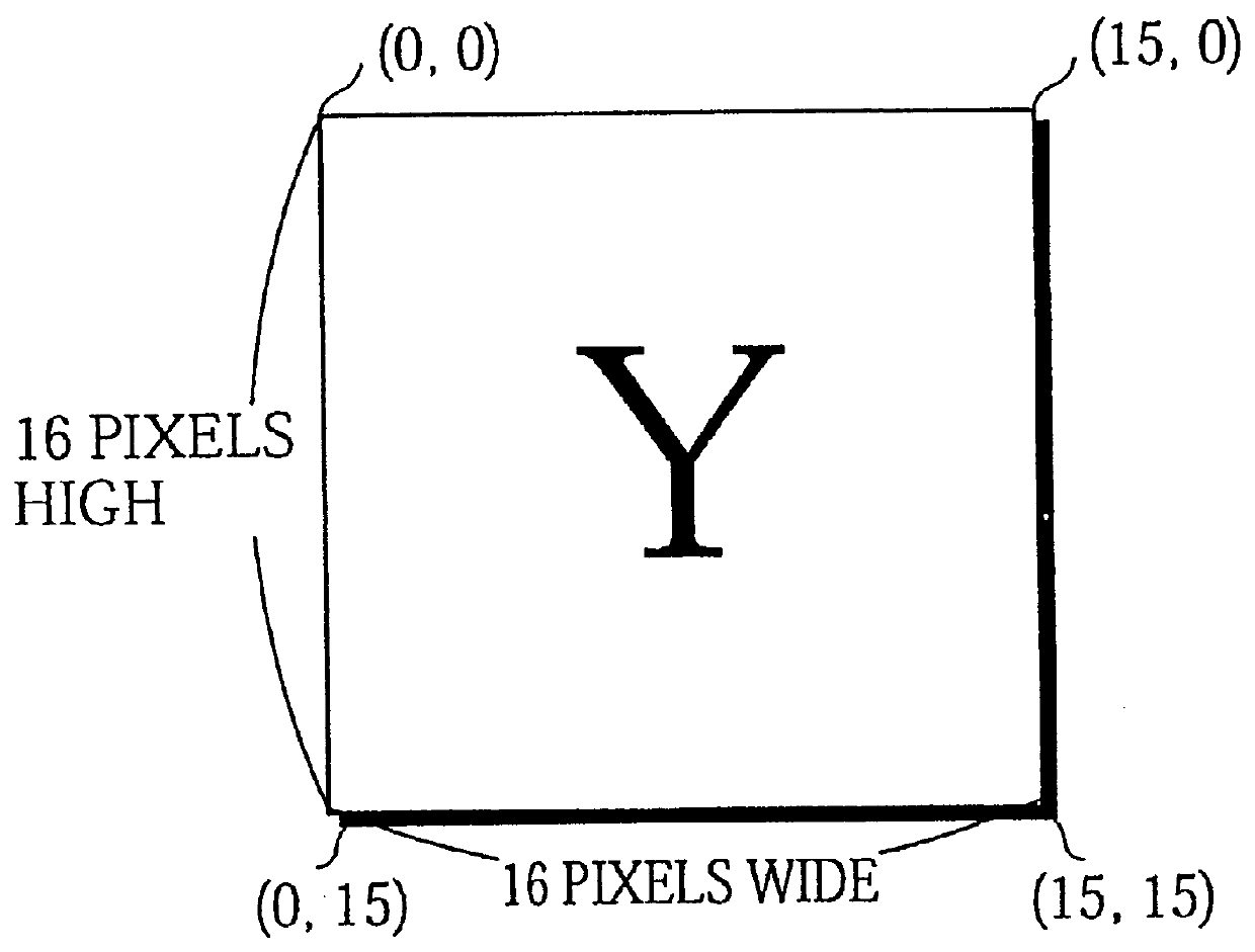
The storage method for luminance components in this second embodiment is shown in FIG. 29A, while the storage method for chrominance components is shown in FIG. 29B. Of special note in FIG. 29A is the storage method for two luminance components in a region of word length composed of one column address in one page. As examples, the luminance components for Y(0,0) and Y(1,0) are stored in the column address 000000.sub.-- 0000, while the luminance components for Y(2,0) and Y(3,0) are stored in column address 000000.sub.-- 0001.

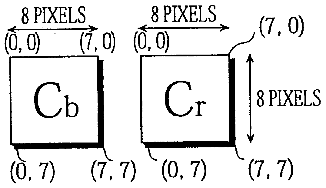
Of special note in FIG. 29B is that a pair of a blue chrominance component and a red chrominance component for the same coordinates are store...


PUM


Abstract

PCT No. PCT/JP97/02995 Sec. 371 Date Apr. 27, 1998 Sec. 102(e) Date Apr. 27, 1998 PCT Filed Aug. 29, 1997 PCT Pub. No. WO98/09444 PCT Pub. Date Mar. 5, 1998An image memory stores a one-screen image by dividing the one-screen image into a plurality of image blocks which are each m pixels wide by n pixels high. The image memory has an array-like storage region storing s*t first chrominance components that compose one image block and s*t second chrominance components that compose the same image block in serial areas between a start area specified by a row address and a first column address and an end area specified by the same row address and a second column address (see FIG. 10). The storage region also stores m*n luminance components that compose the same image block in serial areas between a different start area specified by a different row address and a third column address and an end area are specified by the different row address and a fourth column address.

Description

The present invention relates to an image decoding apparatus used for decoding both video and still images and to an image memory.PRIOR ARTThere is an ever-expanding demand for video decoding apparatuses which are used by a variety of multimedia appliances to decode compressed video data. Such compressed video data is produced by encoding video into digital data where only the differences between successive frames are included to reduce the total data size.When decoding compressed video data, the images to be displayed are produced by combining images used as a reference for differential calculation (hereinafter, "reference pictures") with coded images (hereinafter, "differential pictures") for calculated differences between images.MPEG (Motion Pictures Experts Group) methods use images called I-pictures ("Intra Pictures") as reference pictures. Such I-pictures are compressed image data, but are characterized by including luminance component data and chrominance component data for a...

Claims


Application Information

Patent Timeline
IPC IPC(8): H04N7/26H04N7/50H04N5/907H04N9/64H04N19/00H04N19/423H04N19/426H04N19/44H04N19/46H04N19/503H04N19/59H04N19/61H04N19/625H04N19/70H04N19/85H04N19/91
CPCH04N5/907H04N19/423H04N19/42H04N19/61H04N9/64H04N11/04
Inventor YOSHIOKA, KOSUKEHIRAI, MAKOTOKIYOHARA, TOKUZOKIMURA, KOZO
Owner GK BRIDGE 1
Why Eureka
Try Eureka