Image pickup apparatus with a driving device including an actuator and friction member

Inactive Publication Date: 2000-06-20
MINOLTA CO LTD
View PDF6 Cites 30 Cited by
  • Summary
  • Abstract
  • Description
  • Claims
  • Application Information

AI Technical Summary

Problems solved by technology

Thus, it is difficult to downsize and to lighten the image pickup apparatus.
As a result, size of the apparatus becomes larger and structure of the apparatus

Method used


Image

  • Image pickup apparatus with a driving device including an actuator and friction member
  • Image pickup apparatus with a driving device including an actuator and friction member
  • Image pickup apparatus with a driving device including an actuator and friction member

Examples


first embodiment

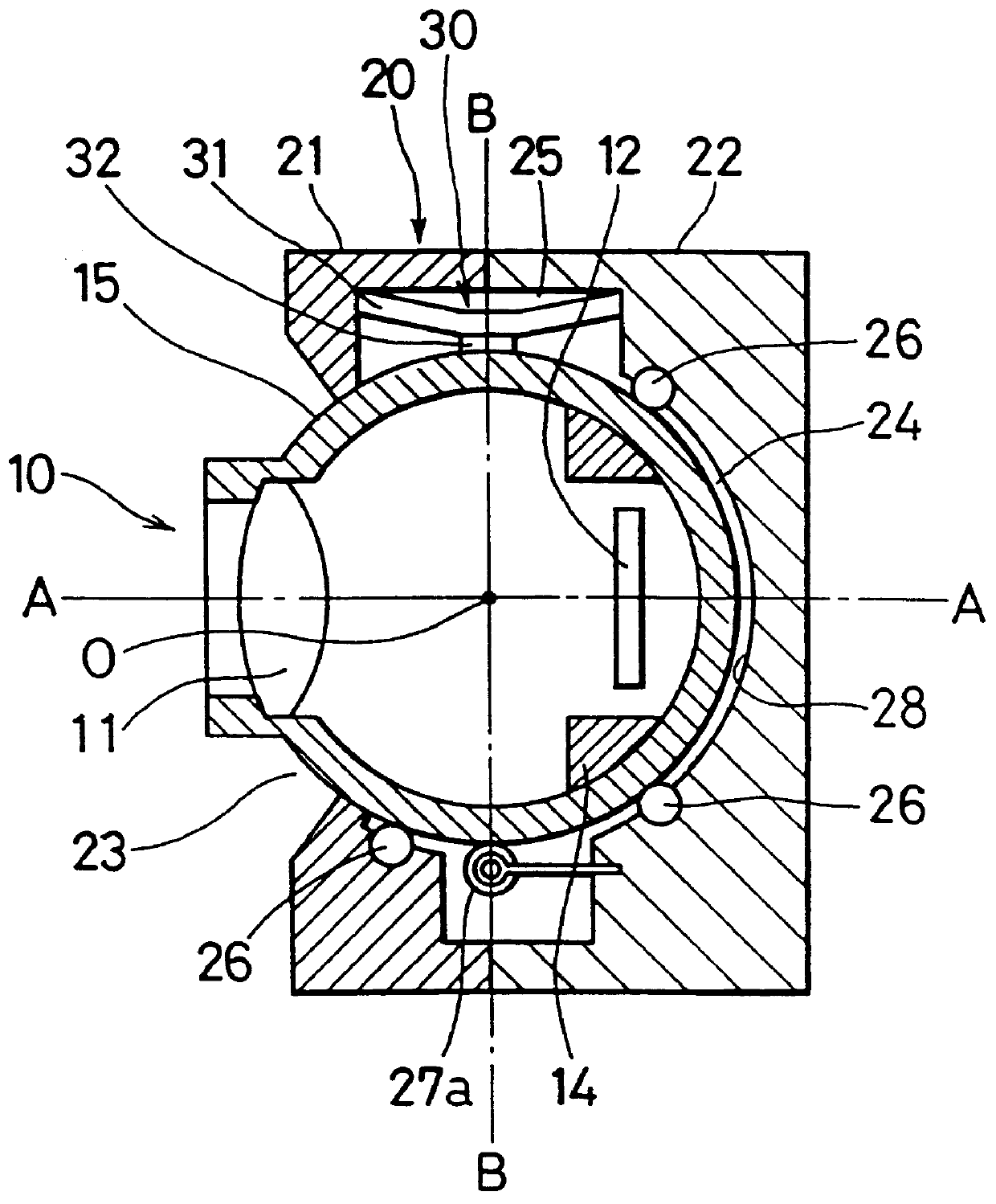
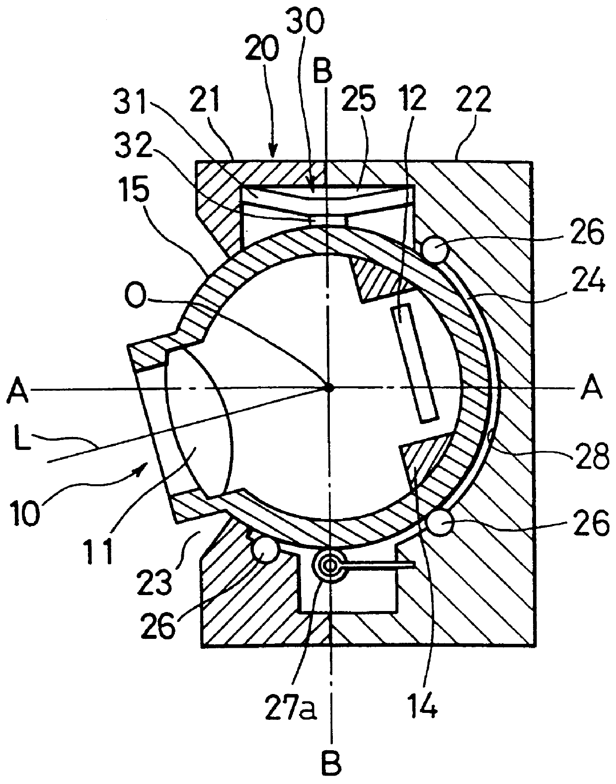
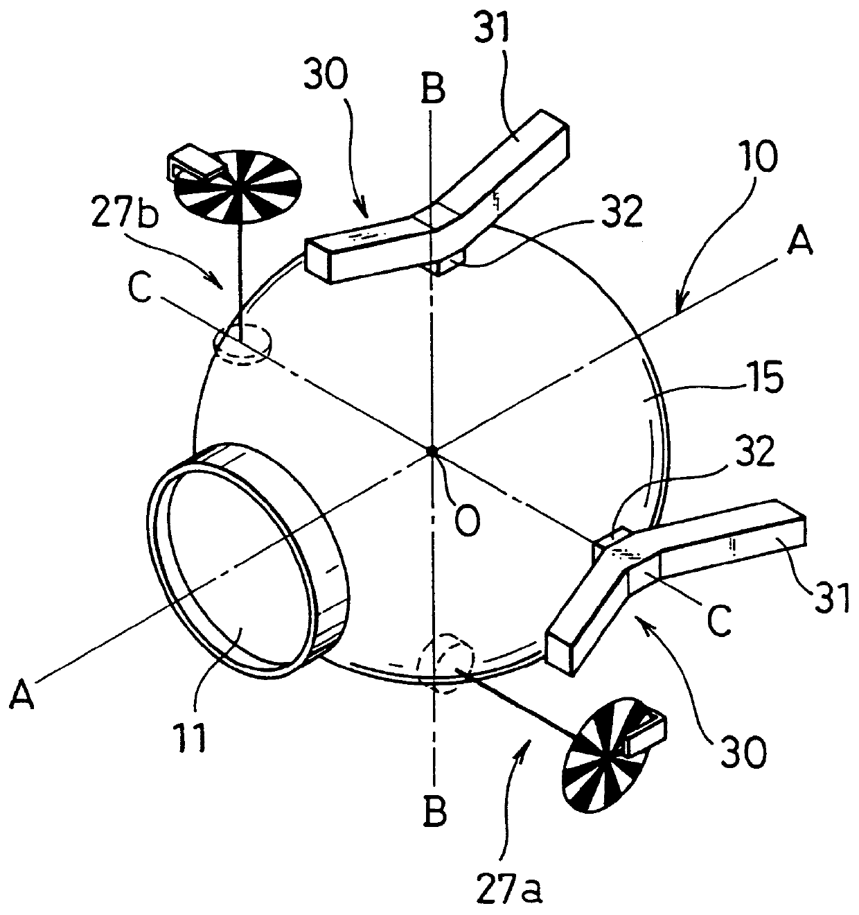
A first embodiment of an image pickup apparatus of this invention is described with reference to the drawings. As can be seen from FIGS. 1 to 3, a portion of an outer surface 15 of an image pickup unit 10 is a spherical surface. A first plane is defined to include an axis A-A and an axis B-B which is parallel to the paper sheet of FIG. 1. A second plane is defined to include the axis A-A and an axis C-C (see FIG. 3) which is perpendicular to the paper sheet. The image pickup apparatus has substantially the same structure on the second plane as the structure on the first plane.

As can be seen from FIGS. 1 and 2, the image pickup unit 10 includes an image pickup optical lens system 11, an image pickup device such as CCD 12 and a balance weight 14. A housing 20 can be separated into a first portion 21 and a second portion 22. The housing 20 has a substantially spherical inside space 24 for containing the image pickup unit 10. An opening 23 is formed on a front face of the housing 20. A ...

second embodiment

A second embodiment of an image pickup apparatus of this invention is described with reference to the drawings. In the above-mentioned first embodiment, two sets of the driving mechanisms 30 respectively including the one-dimensional piezoelectric actuator 31 are used. The second embodiment, however, use only one driving unit with a two-dimensional piezoelectric actuator. Elements designated by the same numerals in the first embodiment are substantially the same as those in the first embodiment. Thus, the explanation of them are omitted.

As can be seen from FIG. 8, a recess 25, in which a driving mechanism 40 is provided, is formed at a back portion with respect to the opening 23 on the concave spherical surface 28 of the space 24. The driving mechanism 40 comprises a two-dimensional piezoelectric actuator 41 and a friction member 42 which is fixed substantially at the center of the two-dimensional piezoelectric actuator 41. As can be seen from FIG. 9B, the two-dimensional piezoelect...

third embodiment

A third embodiment of an image pickup apparatus of this invention is described with reference to the drawings. In the third embodiment, a driving mechanism is provided in a image pickup unit which is a moving portion of the image pickup apparatus. Elements designated by the same numerals as those in the above-mentioned second embodiment are substantially the same, so that the explanation of the elements are omitted.

As can be seen from FIGS. 11 and 12, the driving mechanism 40 is provided on the image pickup unit 10. The driving mechanism 40 is disposed at a position symmetrical to the image pickup optical lens system 11 with respect to the center O of the sphere constituting a convex spherical surface 15 of the image pickup unit 10. The driving mechanism 40 is substantially the same as that in the second embodiment shown in FIGS. 9A and 9B.

Voltages W1 and W2 having sinusoidal waveform with phase difference shown in FIG. 5 are respectively applied to the first arm 41a and the third a...


PUM


Abstract

In an image pickup apparatus for automatically chasing a moving object, an image pickup optical lens system and an image pickup device are contained in a ball shaped unit. A convex spherical surface of the unit is spherically pivoted by a concave spherical surface of an inner space of a housing via ball bearings. A driving mechanism, which alternatively includes two sets of one dimensional piezoelectric actuator and friction member or one set of two-dimensional piezoelectric actuator and a friction member, moves the friction member(s) for trailing an elliptical orbits in two ways. The unit is revolved around an optional axis passing the center of a sphere constituting the convex spherical surface.

Description

This application is based on patent applications No.9-168955, No.9-168956 and No.9-311950 filed in Japan, the contents of which are hereby incorporated by references.1. Field of the InventionThis invention relates to an image pickup apparatus which automatically pursues an object and further relates to a driving device which is suitable for driving the image pickup apparatus.2. Description of the Prior ArtA conventional image pickup apparatus using a ginbal mechanism is shown in FIG. 24. An image pickup optical lens system and an image pickup device such as CCD (Charge Coupled Device), which are not shown in the figure, are contained in a cylindrical image pickup unit 100. The image pickup device is connected to a control unit 130 via a cable K1. The image pickup unit 100 is rotatably pivoted by a shaft 101 on a rotary frame 102. Thus, the image pickup unit 100 can be rotated around Y-axis. The rotary frame 102 is rotatably pivoted by a shaft 103 on a fixed frame 104. Thus, the imag...

Claims


Application Information

Patent Timeline
IPC IPC(8): H04N5/225
CPCH04N5/2251H04N23/50
Inventor UEYAMA, MASAYUKI
Owner MINOLTA CO LTD
Why Eureka
Try Eureka