Truss for fabric covered buildings and the like

a technology for building frames and fabric, applied in the direction of arched structures, structural elements, building components, etc., can solve the problems of high load on wider buildings, inability to withstand the load of standard single-member structures, and high cost of aluminum use, so as to achieve the effect of light weigh

Inactive Publication Date: 2000-07-11
COVER ALL BUILDING SYST
View PDF9 Cites 23 Cited by
  • Summary
  • Abstract
  • Description
  • Claims
  • Application Information

AI Technical Summary

Benefits of technology

It is an object of the present invention to provide a structural truss which is strong en...

Problems solved by technology

However, these wider buildings are subject to much higher loads from wind, snow and so forth.
The standard s...

Method used


Image

  • Truss for fabric covered buildings and the like
  • Truss for fabric covered buildings and the like
  • Truss for fabric covered buildings and the like

Examples


Embodiment Construction

:

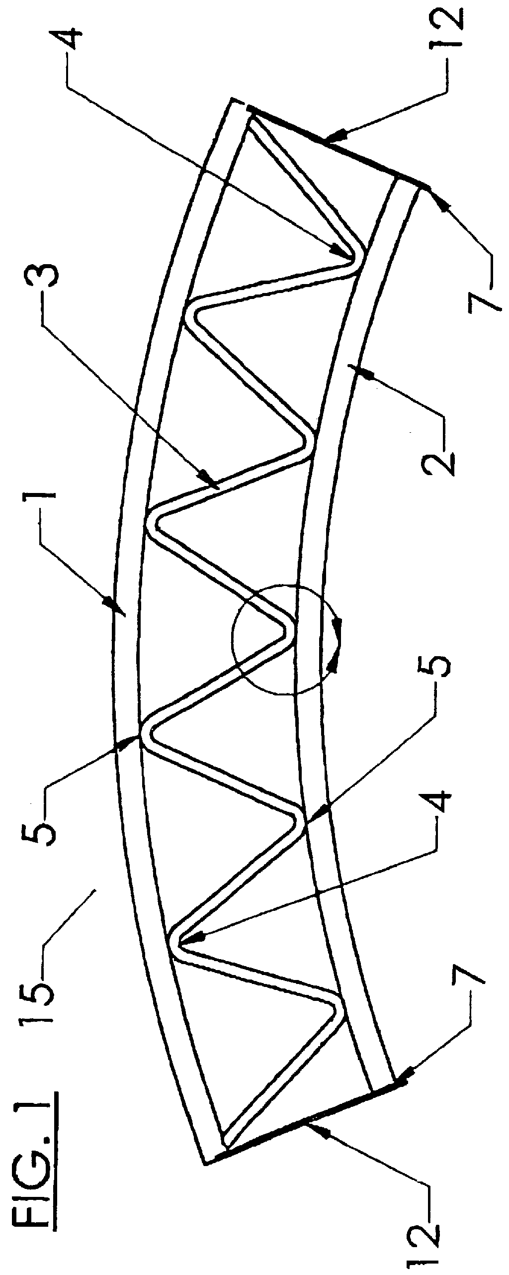
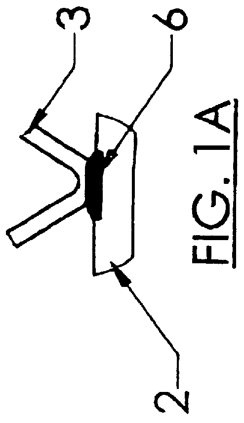
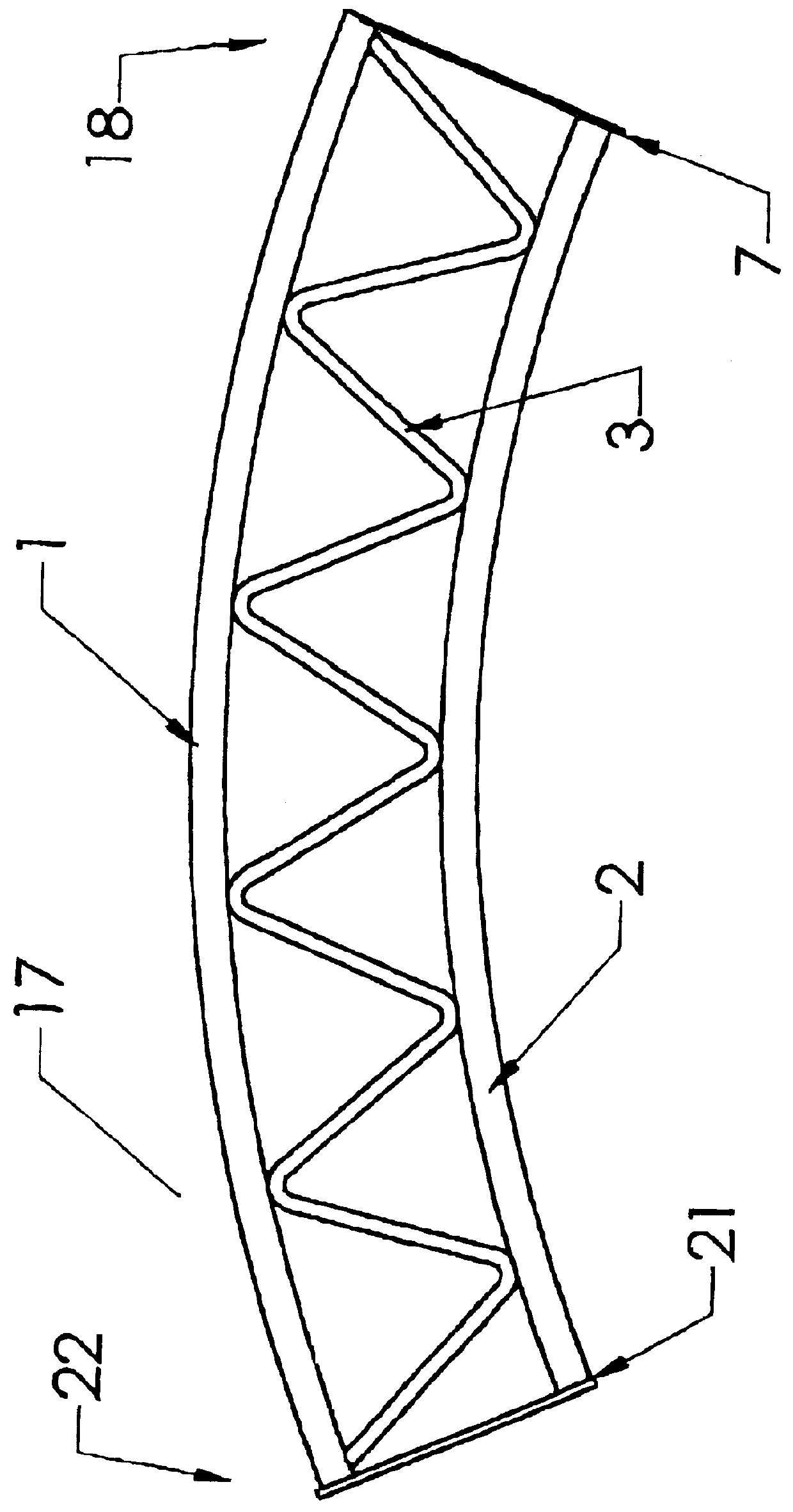
The invention provides a structural truss comprising at least one intermediate section in end to end alignment with two outside sections, each intermediate and outside section comprising a hollow arctuate upper member; a hollow arctuate lower member; a continuous hollow reinforcing web, bent so as to alternately contact the lower side of the upper member and the upper side of the lower member at a number of contact points at which contact points the web is attached to the respective member; a coupling plate at each end of each intermediate section and at one end of each outside section, said coupling plate attached by welding to both said upper member and said lower member, the attachment to the upper member being such that the top edge of said coupling plate is below the upper side of the upper member; and a base plate at the opposite end of each said outside section; section coupling means to connect the coupling plate of one section to the coupling plate of the adjacent section ...


PUM


Abstract

The present invention provides a strong yet lightweight truss which could be used in many applications, and is adapted particularly to a support framework for those fabric covered structures utilizing a fabric stretched over the top of the supporting framework. The truss can be made up into sections comprising tubular upper and lower truss members separated by a continuous tubular web. The coupling plates may be attached to each end of the sections such that the top edge of the coupling plate is below the upper side of the upper member, providing a smooth upper surface to the truss and eliminating wear points which could damage the fabric or other material stretched over or supported by the truss. The truss is easily transported and manufactured.

Description

The invention is in the field of trusses for construction of buildings and in particular such trusses for use in prefabricated, fabric covered buildings, which may be arcuate.BACKGROUND:Fabric covered buildings are well known wherein a plurality of supports, often made of tubing, are erected on a foundation base and held in spaced apart relationship by purlins connected between them. The structure is then covered with fabric, somewhat analogous to a tent. Such buildings are economical, fast and easy to erect and maintain, durable and easy to relocate. These features have made fabric covered buildings very popular, and led to demand for ever longer and wider buildings. However, these wider buildings are subject to much higher loads from wind, snow and so forth. The standard single member arch is unable to withstand these loads.Truss arches, such as that shown in U.S. Pat. No. 5,269,106 to Stafford et al., have been utilized to provide the increased strength need for larger a fabric c...

Claims


Application Information

Patent Timeline
IPC IPC(8): E04B1/32E04B1/342E04B1/19E04C3/04
CPCE04B1/19E04B1/32E04B1/342E04C3/04E04C3/40E04B1/24E04C3/08E04C2003/0491E04B2001/2463E04B2001/2415E04B2001/2457E04C2003/043E04C3/11E04C2003/0486
Inventor QUIRING, RICHARDSTOBBE, NATHAN
Owner COVER ALL BUILDING SYST
Why Eureka
Try Eureka