Unlock instant, AI-driven research and patent intelligence for your innovation.

Side lighted surface light source device having orthogonal projections on light control surface of emission plate and light diffusion member

Inactive Publication Date: 2000-07-11
ENPLAS
View PDF1 Cites 28 Cited by
  • Summary
  • Abstract
  • Description
  • Claims
  • Application Information

AI Technical Summary

Benefits of technology

An object of the present invention is to provide a surface light source device of side light type which solves the above-described problems and outputs a high quality of illumination light highly efficiently in the frontal direction. According to the present invention, the above-described periodic non-uniformity of brightness is suppressed and moire fringe pattern becomes unlikely to occur. In addition, hue of the reflection sheet disposed along the back surface of the guide plate becomes also unlikely to be observed.
The present invention is applied to a surface light source device of side light type that comprises a guide plate having a major surface providing an emission surface and another major surface providing a back surface, a primary light source that supplies illumination light from an incidence surface provided by a side end surface of the guide plate, and a light control member that is disposed along the emission surface and corrects directivity of illumination light emitted from the emission surface.
Each projection of the second control surface has a first slope relatively remote from and a second slope relatively near to the incidence surface of the guide plate and these slopes give an asymmetrical sectional configuration. Namely, angle of inclination .beta.2 of the second slope to a normal that is erected on a general surface of the guide plate is set to be small compared with angle of inclination .beta.1 of the first slope to this normal. It is preferable that angle of inclination .beta.1 of the first slope be smaller than angle of 40 degrees. A light diffusion member may be disposed between the emission surface of the guide plate and the light control member. The light diffusion member decreases difference between the first slope and the second slope in terms of the amount of output light by light diffusion, thereby enhancing uniformity and quality of output light.
The present invention is featured by the first light control surface that is given by the emission surface of the guide plate and the second light control surface that is given by a large number of the asymmetrical projections. The first light control surface provides an efficient directional correction generally toward the frontal direction in a plane parallel with the incidence surface of the guide plate. The second light control surface provides an efficient directional correction generally toward the frontal direction in a plane perpendicular to the incidence surface of the guide plate.
The second light control surface on one hand promotes incidence the first slope which is more likely to contribute to the emission of illumination light and on the other hand suppresses incidence to the second slope which is less likely to contribute to the emission of illumination light. The observation made from the outside (light output side) of the front surface of the light control member gives a predominant visual recognition over a large area corresponding to the first slope 13B. Such a predominant visual recognition is not given by another area corresponding to the second slope 13A because this area is narrow although relatively dark. Therefore, no outstanding visual recognition occurs. After all, fine levels of periodic brightness and darkness are suppressed and brightness also is improved as a whole. The concurrent use of the light diffusion member spreads directional distribution of the propagated light rays to thereby reinforce the action of suppressing the occurrence of fine periodic brightness and darkness.

Problems solved by technology

If a small angle of inclination is given to paired slopes forming the projection of the prism surface of the prism sheet, an increase in output light to the frontal direction will be expected but another problem arises.
This pulsation leads to an undesired periodic non-uniformity of brightness.
If this device is combined with a unit of a structure having another periodicity, e.g., liquid crystal display panel, such periodic non-uniformity of brightness is likely to cause the occurrence of a moire fringe pattern.
The moire fringe pattern remarkably degrades the display quality of the relevant display panel.
This is an undesirable level of phenomenon.

Method used


Image

  • Side lighted surface light source device having orthogonal projections on light control surface of emission plate and light diffusion member
  • Side lighted surface light source device having orthogonal projections on light control surface of emission plate and light diffusion member
  • Side lighted surface light source device having orthogonal projections on light control surface of emission plate and light diffusion member

Examples


Embodiment Construction

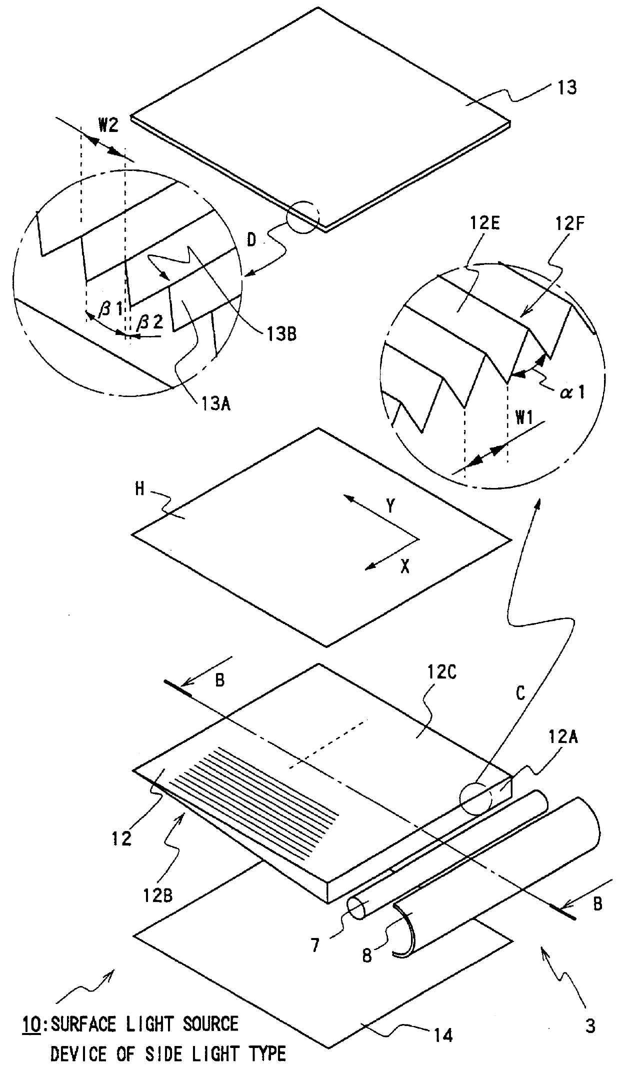
An embodiment of the present invention will now be explained with sequential reference to FIGS. 1 through 8. Except items associated with light control surfaces that are provided by a light control member and a guide plate, this embodiment is common to the conventional technique illustrated in FIGS. 10 and 11. Accordingly, the reference symbols are commonly used as the occasion demands and repeated explanations will be simplified.

First, referring to FIGS. 1 and 2, a surface light source device 10 of side light type is provided with a guide plate 12, primary light source 3, reflection sheet 14, light diffusion sheet H, and prism sheet 13 providing a light control member. The reflection sheet 14, guide plate 12, light diffusion sheet H and prism sheet 13 are laminatedly arranged and are retained by a frame (not illustrated) together with the primary light source 3.

As the reflection sheet 14 there is employed a silver-deposited regular reflection member so as to exhibit a high reflecta...


PUM


Abstract

A surface light source device of side light type is provided with a guide plate, a primary light source, a reflection sheet, and a prism sheet providing a light control member. An emission surface of the guide plate provides a light control surface (arrow C). The light control surface has a large number of minute projections each of which extends generally orthogonal or slightly obliquely to an incidence surface. Each projection has a pair of slopes. A surface of a light control member (prism sheet) is opposite with the guide plate to provide another light control surface (arrow D). Projections on the light control member extend generally in parallel with the incidence surface of the guide plate and each have first and second slopes which are relatively remote from and relatively near to the incidence surface, respectively. Inclination angle beta 2 of the second slope (as defined with respect to a normal erected on a general surface of the guide plate) is small compared with inclination angle beta 1 of the first slope. Inclination angle beta 2 may be smaller than, for example, 40-degrees. A light diffusion member may be disposed between the emission surface of the guide plate and the light control member.

Description

1. Field of the InventionThe present invention relates to a surface light source device of side light type. The present invention is applied to, for example, a back lighting of a liquid crystal display.2. Related ArtA surface light source device of side light type has been applied to, for example, a liquid crystal display and illuminates the liquid crystal display from its back. This disposition is suitable for a thin configuration of the device.Usually a rod-shape light source such as a cold cathode tube is employed as a primary light source with respect to the surface light source device of side light type, wherein this rod-shape light source is disposed sidewardly of a guide plate (a plate-like light guiding member). Illumination light that has been emitted from the primary light source is introduced into the guide plate by passing through a side end surface thereof The introduced illumination light propagates through the guide plate and, in this process, light emission occurs fr...

Claims


Application Information

Patent Timeline
IPC IPC(8): F21V8/00F21V5/00F21V5/02G02B6/00G02B5/02G02F1/1335G02F1/13357G09F9/00
CPCF21V5/02G02B6/0016G02B6/0038G02B6/0053G02B6/0036
Inventor OHKAWA, SHINGO
Owner ENPLAS
Features
  • R&D
  • Intellectual Property
  • Life Sciences
  • Materials
  • Tech Scout
  • Unparalleled Data Quality
  • Higher Quality Content
  • 60% Fewer Hallucinations
Learn More