Secure enclosure bolt work apparatus for automated banking machine

a technology for working apparatus and secure enclosure, which is applied in the direction of safes, wing accessories, instruments, etc., can solve the problems of increasing confusion, incorrect panel assembly into the enclosure, and production process problems, and achieve the effect of reducing the vulnerability of the hinges

Inactive Publication Date: 2000-07-18
INT VAPOR POWER
View PDF7 Cites 61 Cited by
  • Summary
  • Abstract
  • Description
  • Claims
  • Application Information

AI Technical Summary

Benefits of technology

It is a further object of the present invention to provide a method of making a secure enclosure for an automated banking machine that is more readily accomplished.
The hinge assemblies used for connecting the door and the hinge side panel enable connection of the hinges together even when the hinges are misaligned. In addition the hinge assemblies enable independent vertical adjustment so that the door may be positioned to close the opening of the secure enclosure.

Problems solved by technology

Problems in production processes may arise when enclosures are assembled from panels of similar size.
If care is not exercised, an incorrect panel may be assembled into the enclosure.
The potential for confusion increases when several enclosures of similar size are being manufactured from similar panels, which enclosures have different openings to accommodate the positions of devices in the ATM in which the enclosure is used.
The improper manufacture of an enclosure generally results in a significant amount of scrap material, as well as wasted fabrication labor.
Hinges are often a site for attack by burglars.
This avoids misalignment but can be burdensome from an assembly standpoint.
When components of the hinge assemblies are attached to the door and enclosure in separate operations it is not uncommon to encounter situations where the hinges are slightly misaligned.
In such circumstances it may not be possible to mount the door on the enclosure without considerable rework.
Even if the door can be mounted on the hinges, it may not be properly positioned to enable closing the opening of the enclosure.
Again, in such circumstances costly rework is required to make the secure enclosure suitable for use in an automated teller machine.
However, providing enhanced security also often comes with a high degree of complexity.
This increases the cost of the automated banking machine.
Complex mechanisms can also make it more difficult for authorized personnel to gain access to the secure enclosure.

Method used


Image

  • Secure enclosure bolt work apparatus for automated banking machine
  • Secure enclosure bolt work apparatus for automated banking machine
  • Secure enclosure bolt work apparatus for automated banking machine

Examples


Embodiment Construction

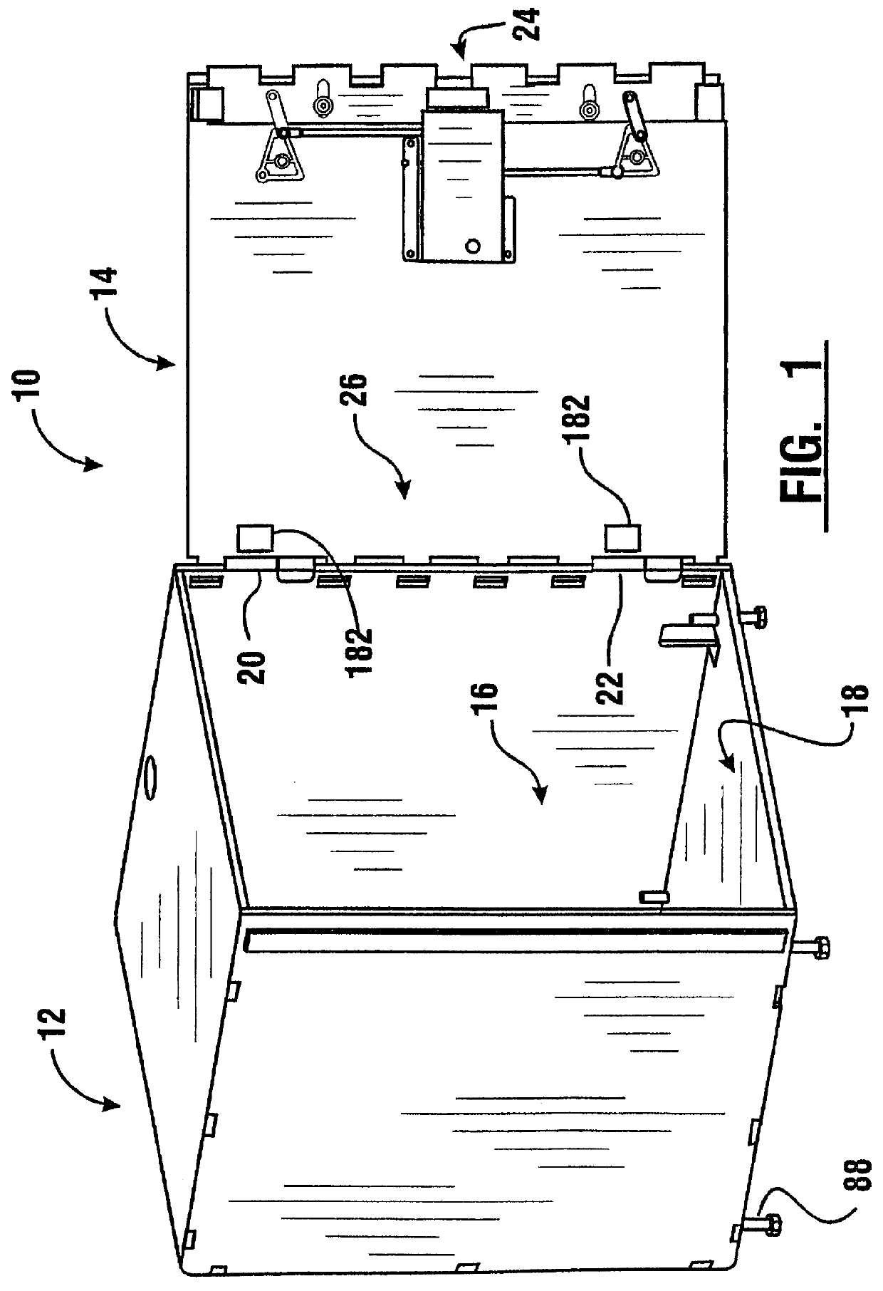
Referring now to the drawings and particularly to FIG. 1, there is shown therein a secure enclosure for an automated banking machine of a preferred embodiment of the present invention, generally indicated 10. It should be understood that the secure enclosure is part of a larger automated banking machine, such as an ATM or similar apparatus. The secure enclosure 10 includes a generally rectangular chest portion 12 and a moveable door 14. The chest portion 12 bounds an interior area 16 which has an opening 18 at a rear side of the chest. Door 14 is sized for closing opening 18. Door 14 is attached to chest portion 12 by an upper hinge assembly 20 and a lower hinge assembly 22.

Door 14 has mounted thereon a locking bolt mechanism 24. Door 14 further includes a dead bolt portion 26. The locking bolt mechanism 24 and the dead bolt portion 26, as later described in detail, are operative to secure the door in position closing opening 18.

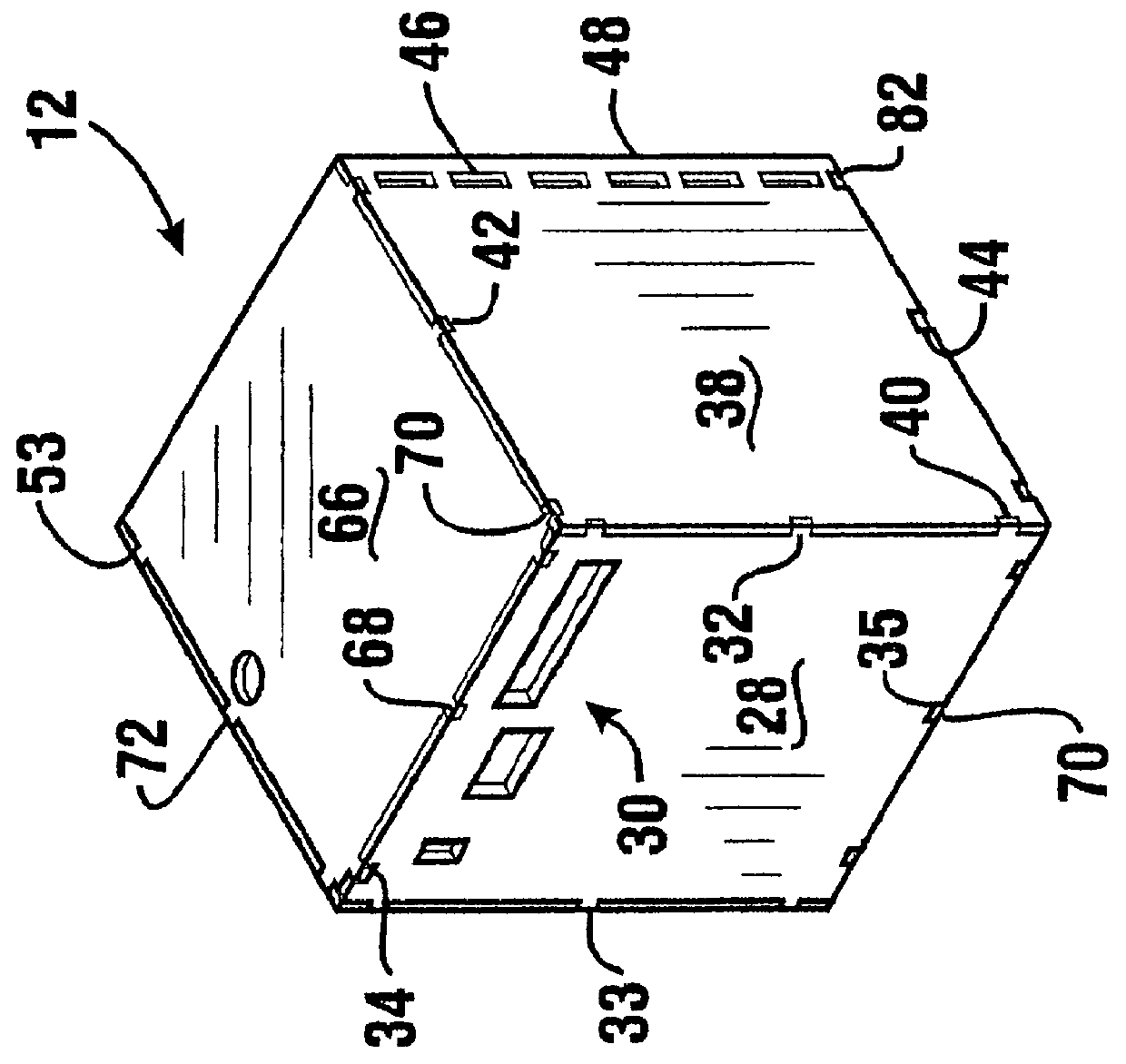
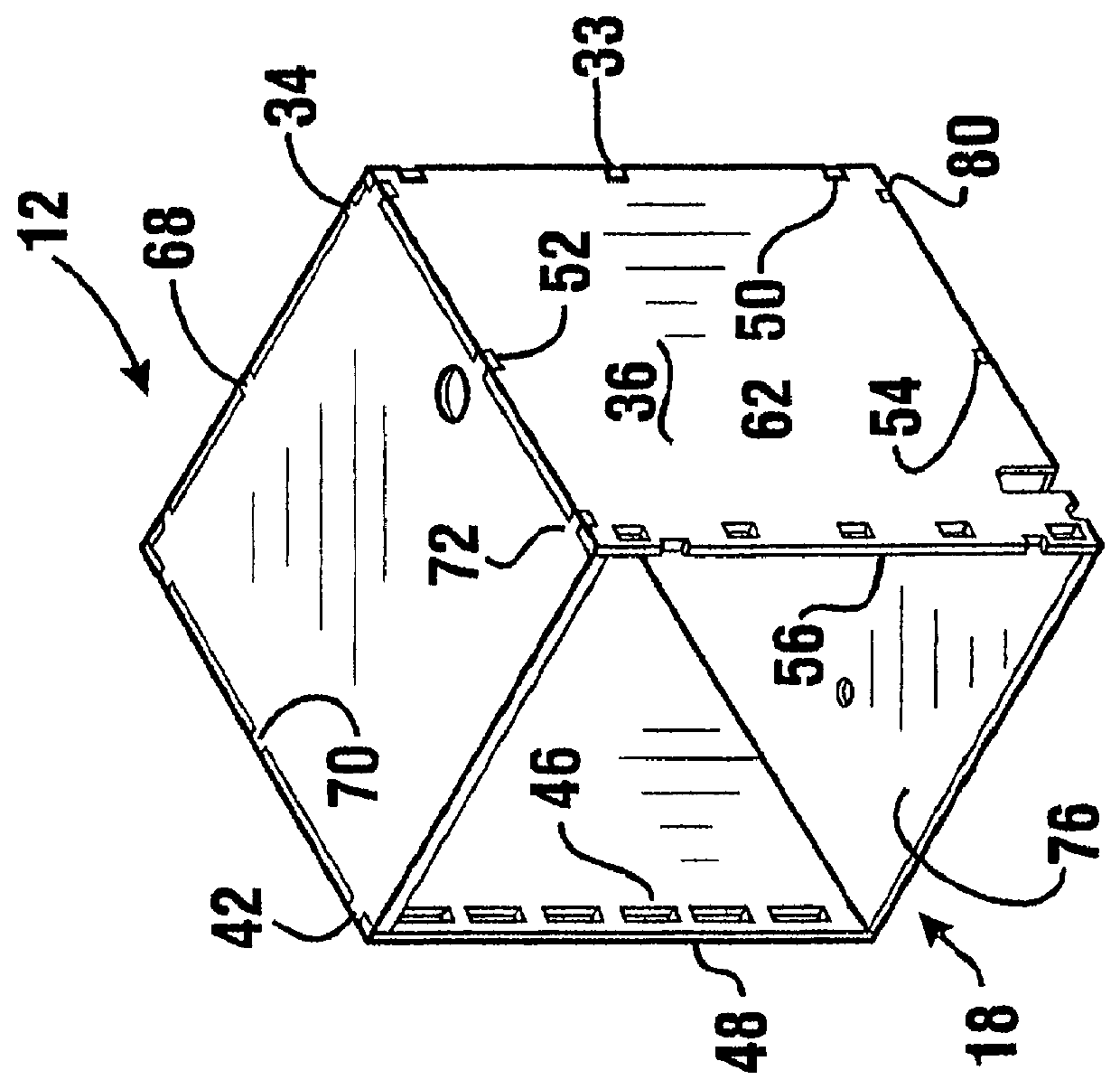
As shown in FIGS. 2 and 3 the chest portion of the sec...


PUM


Abstract

PCT No. PCT / US97 / 22510 Sec. 371 Date Mar. 16, 1999 Sec. 102(e) Date Mar. 16, 1999 PCT Filed Nov. 25, 1997 PCT Pub. No. WO98 / 26380 PCT Pub. Date Jun. 18, 1998A secure enclosure (10) for an automated banking machine includes a chest portion (12) and a moveable door (14). The door of the secure enclosure has mounted thereon a locking bolt work mechanism (24) which operates in a secure condition to engage locking bolt engaging apertures (46). The door further includes dead bolt projections (150) which engage apertures (62) when the door is in the closed position. The bolt work mechanism includes a drive cam (122) which is engageable by a member of a lock (126). The drive cam is connected to a pair of idler cams (118, 120) by L-links (134, 136). The idler cams are connected to a locking bolt (102) by S-links (138, 140). Movement of the drive cam enables moving the locking bolt between extended and retracted positions.

Description

This invention relates to automated banking machines. Specifically this invention relates to a method of making a secure enclosure for an automated banking machine, which enclosure includes a secure door more readily manufactured and assembled, and which provides enhanced security.Automated banking machines are known in the prior art. Popular automated banking machines often used by consumers are automated teller machines (ATMs). ATMs are increasingly used by consumers to conduct banking transactions. Common banking transactions conducted by consumers at ATMs include deposits, withdrawals, account transfers and balance inquiries.Most ATMs include a secure enclosure. The secure enclosure is used to hold currency and other valuable items inside the machine. Deposits made by customers into an ATM are also preferably held within a secure enclosure until they can be removed by authorized personnel. The secure enclosure also preferably houses portions of the mechanisms used for receiving ...

Claims


Application Information

Patent Timeline
Patent Type & Authority Patents(United States)
IPC IPC(8): E05D7/14E05G1/00E05D7/00E05G1/026E05C9/02E05C9/00E05C19/00G07F19/00E05D11/00E05D5/02E05D11/04E05D5/00
CPCE05C9/02E05C19/001E05D7/0027E05D7/14E05G1/00E05G1/026G07F19/20G07F19/205E05D5/0215E05D5/023E05D11/04E05Y2900/132Y10T292/0963Y10T292/0964
Inventor DUNLAP, RICHARD E.HARRY, DONALD W.SEDLOCK, GERALD T.VANKIRK, THOMAS A.ANTRAM, HOWARD E.KALINOWSKI, JOSEPH M.MERCER, SCOTT A.COX, PAUL J.KONTOR, KENNETH C.GRAEF, H. THOMAS
Owner INT VAPOR POWER
Why Eureka
Try Eureka