Dynamically controlled routing using dynamic management of intra-link traffic to virtual destination nodes

Inactive Publication Date: 2000-07-18
NORTEL NETWORKS LTD
View PDF12 Cites 41 Cited by
  • Summary
  • Abstract
  • Description
  • Claims
  • Application Information

AI Technical Summary

Benefits of technology

Various objects, features, aspects and advantages of the present invention will become more apparent from the following detailed description, taken in conjunction with the accompanying drawings, of preferred embo

Problems solved by technology

One aspect susceptible of improvement is the procedure governing the way in which a call exits the DCR network for a final destination outside the DCR network, possibly in another network.
Although the network could be reconfigured to allow other networks

Method used


Image

  • Dynamically controlled routing using dynamic management of intra-link traffic to virtual destination nodes
  • Dynamically controlled routing using dynamic management of intra-link traffic to virtual destination nodes
  • Dynamically controlled routing using dynamic management of intra-link traffic to virtual destination nodes

Examples


Example

1. The DCR Network (without virtual destination nodes)

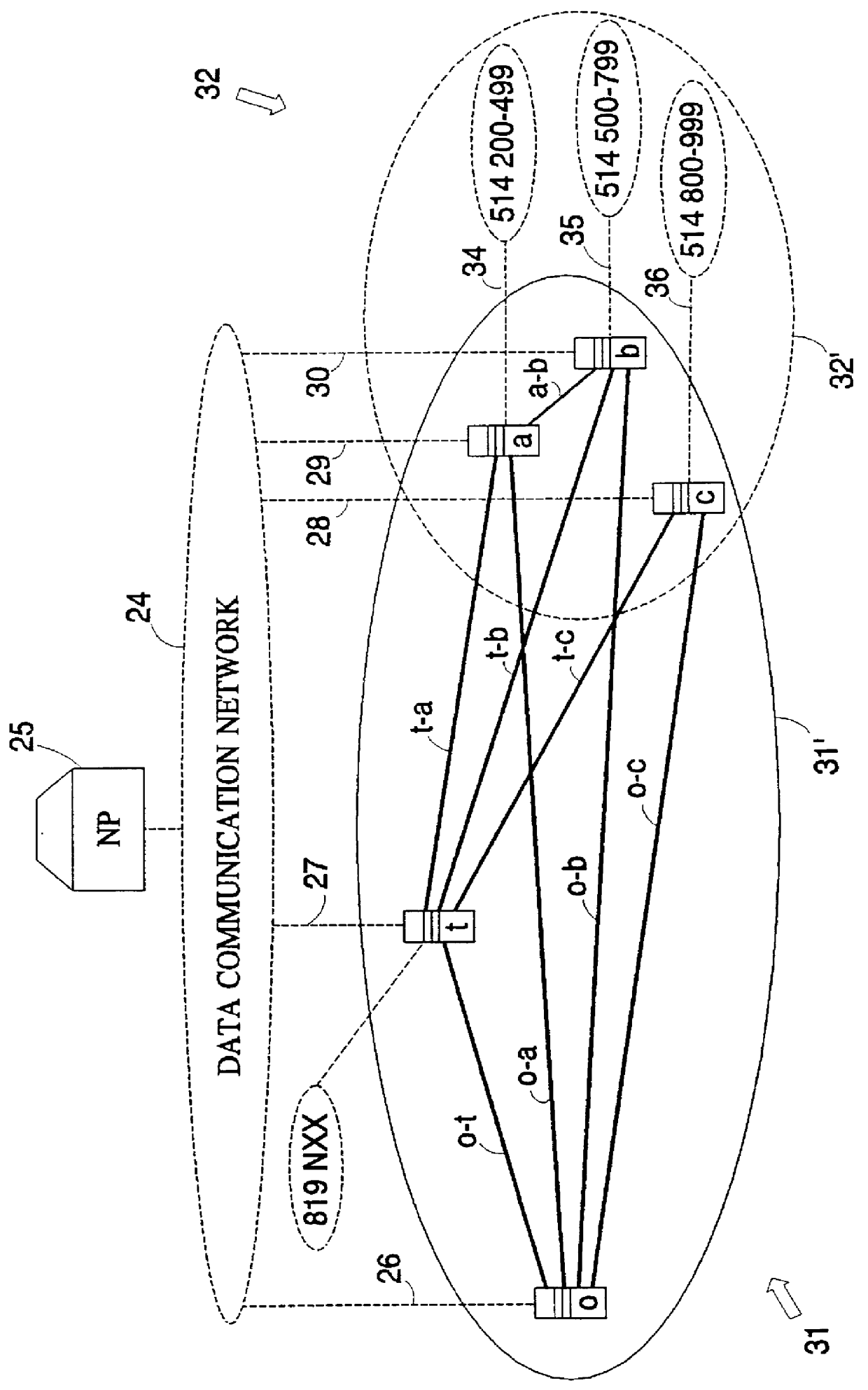
Before the preferred embodiments of the invention are described, a simplified DCR network, and its operation, will be described briefly with reference to FIG. 1 in order to facilitate comprehension of how and where the virtual destination nodes of the present invention are to be implemented. For purposes of illustration only, the DCR network 31 illustrated in FIG. 1 is shown as comprising five circuit switches interconnected by sets of circuit groups. Lower case letters o, t, a, b and c have been used to designate the switches and the circuit groups are identified by pairs of letters o-t o-a, o-b, o-c, t-a, t-b, t-c and a-b, representing the two switches they are connecting.

It should be noted that a circuit group may be two-way. In the DCR network 31 all circuit groups are two-way. For example, circuit group o-t is used from o to t and from t to o.

A data communications network 24 connects a network processor 25 to the switches o,...


PUM


Abstract

PCT No. PCT/CA95/00600 Sec. 371 Date Apr. 24, 1997 Sec. 102(e) Date Apr. 24, 1997 PCT Filed Oct. 26, 1995 PCT Pub. No. WO96/13945 PCT Pub. Date May 9, 1996A DCR telecommunications network comprises a plurality of network switching elements interconnected by circuit groups for carrying calls, and a network processor communicating with the network elements. If it cannot use a direct route to a neighbouring network element, the switching element may access a routing table containing alternate routes which are updated periodically by the network controller. The network functions as a group of nodes interconnected by links. Routing takes place on a node-to-node basis. At least one of the nodes is a virtual destination node, vis. a logical entity corresponding to a group of two or more components which are network elements. A link to the virtual destination node is a set of circuit groups connecting to its components. Final destinations outside the network can be associated with the virtual destination node as an intermediate destination node, thereby allowing a call to exit the DCR network via any of the components rather than via only one Unique Exit Gateway. Where a link to the virtual destination node comprises a plurality of circuit groups, the associated switching element stores proportions for those circuit groups. When attempting to route a call via the link to the virtual destination node, the switching element attempts the circuit groups in dependence upon the proportions. The proportions may be fixed, i.e. computed off-line and stored. Alternatively, the proportions may be updated by the network processor based upon call completion information it receives periodically from the switching elements.

Description

This invention relates to telecommunications networks and, in particular, to telephone networks employing dynamically controlled routing of calls.For many years, the standard call routing method used by most North American telephone companies has been fixed hierarchical routing (FHR). In networks employing FHR, calls are sent from their origin network node to their destination network node along routes comprising a predetermined sequence of connection paths using circuit groups (truck groups) between successive nodes. At an origin node, a call is offered first to a direct circuit group. If all direct circuits are busy, the call is routed via a transit node. Should this alterative route prove to be busy as well, the network continues to search for a path, selecting alternative routes in a fixed, predetermined sequence from the most-direct to the least-direct route. Finally, if no connecting route can be found, the network blocks the call. The predetermined sequence of alternative rou...

Claims


Application Information

Patent Timeline
IPC IPC(8): H04Q3/00H04Q3/64H04Q3/66H04M3/00H04Q3/76H04Q3/545
CPCH04Q3/002H04Q3/0025H04Q3/66H04Q2213/13097H04Q2213/13098H04Q2213/13102H04Q2213/13103H04Q2213/13104H04Q2213/13164H04Q2213/13176H04Q2213/13345
Inventor BEDARD, FRAN.CEDILLA.OISREGNIER, JEANCARON, FRANCE
Owner NORTEL NETWORKS LTD
Why Eureka
Try Eureka