Technique for providing end-to-end congestion control with no feedback from a lossless network

a lossless network and congestion control technology, applied in the field of communication networks, can solve the problems of inability to provide end-to-end congestion control

Inactive Publication Date: 2006-04-25
INFINISWITCH CORP +1
View PDF6 Cites 244 Cited by
  • Summary
  • Abstract
  • Description
  • Claims
  • Application Information

AI Technical Summary

Benefits of technology

[0026]Advantageously, the present invention provides a technique that prevents the source from transmitting more data into the network than a network bottleneck can sustain, thereby obviating injection of excess data into the network. The invention also provides a mechanism to determine a flow rate level that the network can support and communicate that level to the source. Moreover, the determination is made on a regular basis so that subsequent flows can be adjusted to either increase or decrease their rates based on the most current conditions.

Problems solved by technology

IB switches typically utilize flow control with very little buffering because the RTT for a link is typically very small.
Yet, that information always “lags” current network conditions because of the time it takes to generate and deliver the message.
In contrast, if the buffers in an on / off flow control scheme are not sufficient to cover the RTT, then it is possible to lose data due to buffer overrun.
A problem arises when the link-by-link flow control scheme is used in connection with a fair allocation bandwidth policy implemented by the switches of a network. FIG. 1 is a schematic block diagram of a conventional communications network 100 having a plurality of switches interconnected by point-to-point links.
However, this is not possible even though L2 and L4 can easily accommodate such bandwidth.
This is because the flow control scheme limits the bandwidth according to the fair arbitration policy operating on the switches.
As a result, the buffering fills and empties too quickly for an average occupancy to be meaningful as a way to indicate congestion and dropping packets is not allowed as a way to provide feedback to the source.
In this type of a network, the links are subject to congestion spreading effects if the end nodes do not reduce their outputs to an amount sustainable through a bottleneck rate of the network.
Congestion arises when a flow of transmitted data meets another flow at a point that both must share such that data “backs up” the receive buffer at this point, requiring flow control back to the source.
However, the network-supported rate may change over time.
Thereafter, when the average exceeds a threshold, packets are randomly either dropped or marked, or eventually the buffers fill and overflow, resulting in lost packets.
A problem with using such schemes in an lB communications network is the desired property of the network that it specifically avoid the loss of packets.
With buffering only for delays associated with transmitting flow control information back to the source of a link and no packet loss, it is not feasible to use these prior art schemes in an IB switch to identify congestion and mark packets.
However, this scheme uses complex estimators and relies only on those estimators for setting specific transfer rates.
Subsequent work showed practical difficulties in using an averaged inter-packet gap as a sole control variable.

Method used


Image

  • Technique for providing end-to-end congestion control with no feedback from a lossless network
  • Technique for providing end-to-end congestion control with no feedback from a lossless network
  • Technique for providing end-to-end congestion control with no feedback from a lossless network

Examples


Embodiment Construction

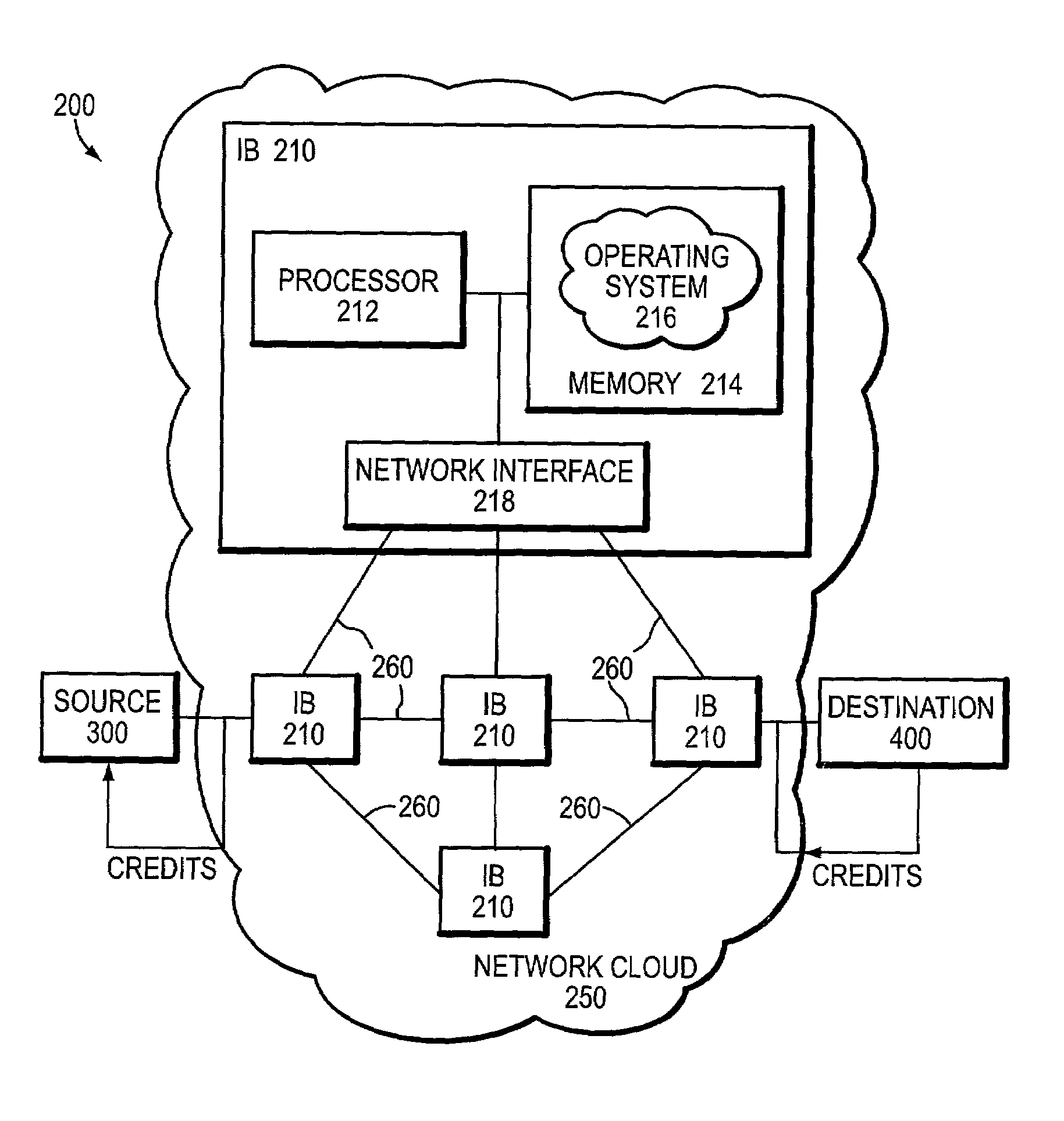
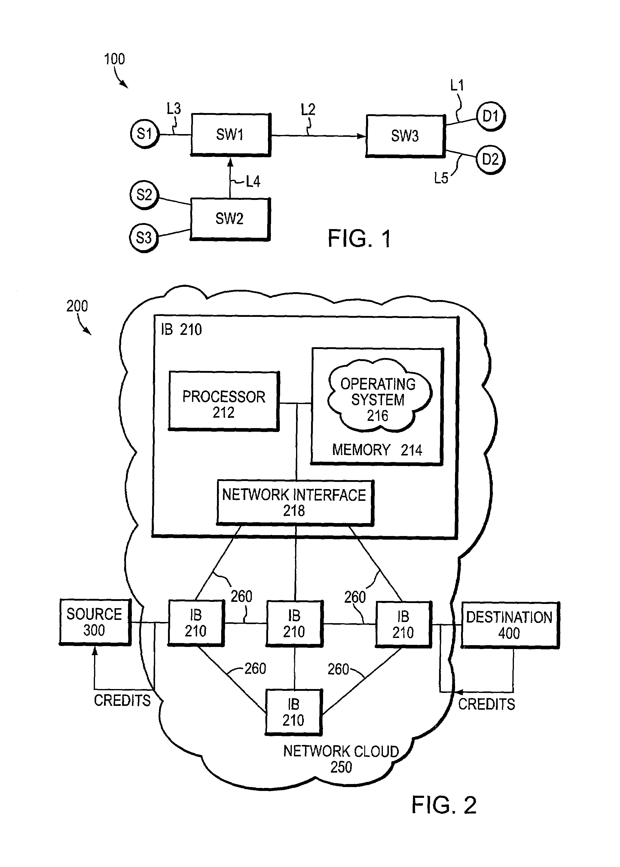
[0033]FIG. 2 is a schematic block diagram of a communications network 200, such as an InfiniBand (IB) communications network, that may be advantageously used with the present invention. The network 200 comprises a source end node (source) 300 and a destination end node (destination) 400 interconnected by a network cloud 250 of communication links 260 coupled to intermediate nodes 210. The links 260 are preferably point-to-point, unidirectional links arranged in a full-duplex communication configuration and capable of accommodating different transfer data rates or speeds. The nodes are computers that may be embodied as servers (end nodes) and / or intermediate nodes (routers or switches).

[0034]Each node, e.g., intermediate node 210, comprises a plurality of interconnected resources, including a processor 212, a memory 214 and an input / output device, such as a network interface 218. The memory 214 may comprise storage locations addressable by the processor and interface for storing soft...


PUM


Abstract

A congestion management technique achieves an end-to-end data flow rate that is supported by a lossless communications network. The end-to-end rate extends from a source end node to destination end node of the network and is preferably at or slightly below a bottleneck rate of the network. The destination end node determines, on its own and without any help from network elements, a supportable rate of activity in the network and provides feedback to the source end node. By achieving such a rate, data transmitted by the source end node can flow through the network without loss of packets and without the use of substantial buffering.

Description

FIELD OF THE INVENTION[0001]The present invention relates to communications networks and, more specifically, to a technique for controlling congestion in a lossless communications network.BACKGROUND OF THE INVENTION[0002]Communication in a computer network involves the exchange of data between two or more entities interconnected by communication links. These entities are typically software programs executing on computer platforms, such as end nodes and intermediate nodes. An example of an intermediate node may be a router or switch which interconnects the communication links to enable transmission of data between the end nodes, such as a server having processor, memory and input / output (I / O) storage resources.[0003]Communication software executing on the end nodes correlate and manage data communication with other nodes. The nodes typically communicate by exchanging discrete packets or frames of data according to predefined protocols, such as the Transmission Control Protocol / Intern...

Claims


Application Information

Patent Timeline
Patent Type & Authority Patents(United States)
IPC IPC(8): G08C15/00
CPCH04L47/10H04L47/115H04L47/39H04L47/215H04L47/283H04L47/18
Inventor SIMCOE, ROBERT J.
Owner INFINISWITCH CORP
Why Eureka
Try Eureka