Multi-frequency band receiver for RF signal

a multi-frequency band, receiver technology, applied in the direction of electrical equipment, substation equipment, angle demodulation by oscillation conversion, etc., can solve the problems of poor coverage of another network, failure of connection between and failure of mobile telephone and mobile telephone network

Inactive Publication Date: 2000-07-18
UNWIRED PLANET
View PDF12 Cites 32 Cited by
  • Summary
  • Abstract
  • Description
  • Claims
  • Application Information

AI Technical Summary

Benefits of technology

Yet another advantage of the invention is the following. Two different methods are used when mixing from the RF area to the baseband frequency area in the inventive multiple band receiver. This enables the reception of radio communication systems having different requirements on the receiver performance.
is the following. Two different methods are used when mixing from the RF area to the baseband frequency area in the inventive multiple band receiver. This enables the reception of radio communication systems having different requirements on the receiver performance.
The invention will be described in more detail in the following, by means of preferred embodiments and with reference to the enclosed drawings.
FIG. 1 is a simplified block diagram of a transceiver apparatus;
FIG. 2 is a scheme over an embodiment of a multiple band receiver according to the invention.

Problems solved by technology

Establishing a connection between a mobile telephone and a mobile telephone network often fails when the network is heavily loaded, since the mobile telephony network has a certain maximum capacity limiting the accessibility of the network.
Connections fail particularly often in densely populated areas where peaks occur at certain times of the day.
In some areas one system may have a good coverage while the coverage of another network is poor.
A disadvantage of this solution is that the radio frequency is mixed twice before the I / Q demodulation, which increases the power consumption.
Another disadvantage of this solution is that in order to receive two different radio frequency systems with the receiver, they must have the same channel bandwidth.
The receiver does not work for radio frequency systems having different channel bandwidths.
One disadvantage associated with this solution is that the additional unit must be brought along to make it possible to connect the mobile telephone to both the systems.
Another disadvantage is that when a signal is received, a mixing is performed to a first intermediate frequency.
This mixing implies an unnecessary power loss for the power supply.
Yet another disadvantage of this receiver is that also this receiver requires that the two digital cellular systems to be received must have the same channel bandwidth.

Method used


Image

  • Multi-frequency band receiver for RF signal
  • Multi-frequency band receiver for RF signal

Examples


Embodiment Construction

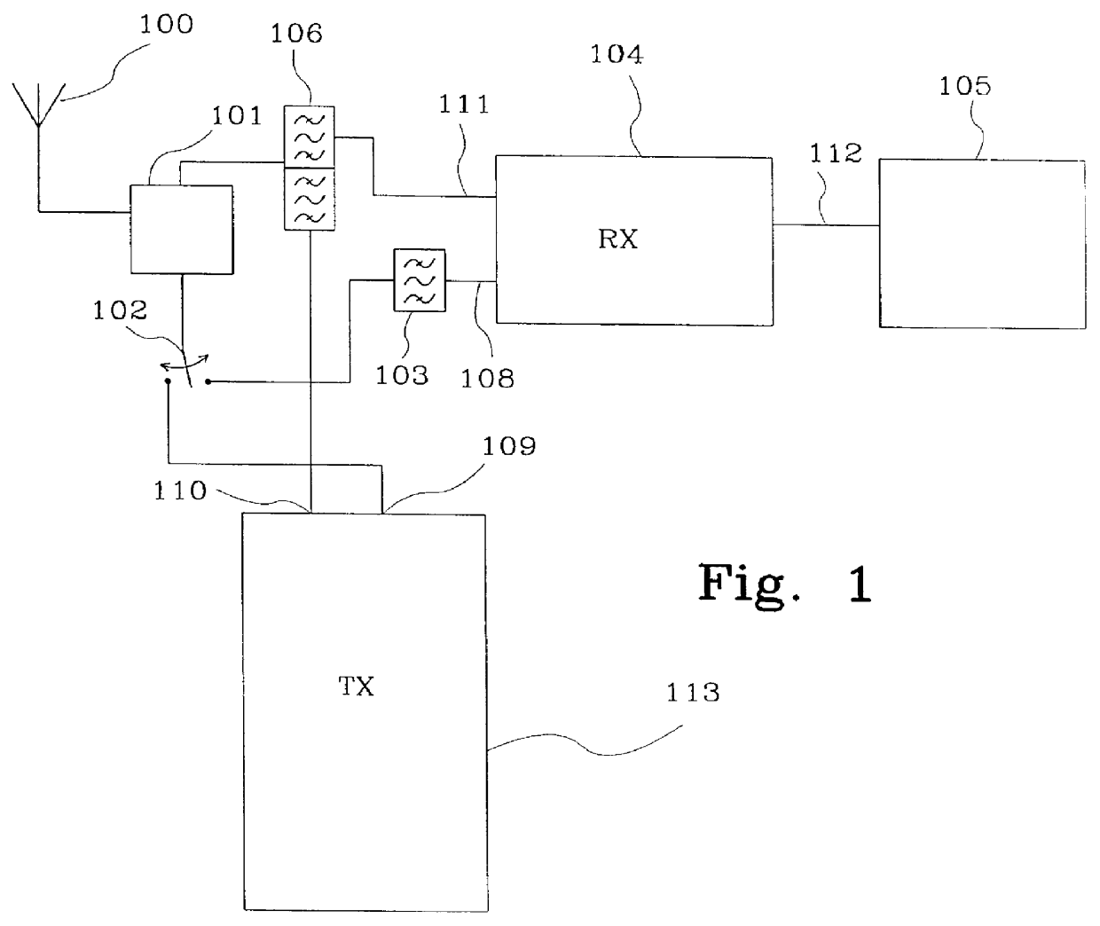
FIG. 1 is a schematic diagram of a transceiver apparatus in, for example, a mobile telephone for radio communication. The transceiver comprises an antenna 100, an antenna combination unit 101 and a switch 102. The switch connects both a multiple band receiver 104 via a bandpass filter 103 and a transmitter 113 to the antenna combination unit 101. The transceiver apparatus further comprises a duplex filter 106 connecting the transmitter 113 and the multiple band receiver 104 to the antenna combination unit 101. The receiver 104 is arranged to receive signals in several different frequency bands for different types of mobile telephone systems in the radio frequency (RF) area. The different types of mobile telephony systems can also have different channel spacing. The mobile telephony systems may be, for example, AMPS in the frequency band 869-894 MHz with 30 kHz channel spacing, and PCS in the frequency band 1930-1990 MHz with 200 kHz channel spacing.

Other mobile telephone systems in ...


PUM


Abstract

The present invention relates to a receiver device comprising a receiver (104) adapted to receive radio signals in two frequency bands (FB1, FB2). The radio signals in one of the frequency bands (FB1) constitute communication signals for a radio system (AMPS, NMT) having a certain channel spacing, whereas the radio signals of the second frequency band (FB2) constitutes communication signals for a second radio system (PCS1900, DCS1800, GSM) having a second certain channel spacing. The receiver (104) comprises two inputs (108, 11) each intended for a radio system having different frequency bands and channel spacing. For radio signals occurring on one input (108), mixing is performed from the RF range directly to the baseband frequency range. For radio signals occurring on the second input (108) the mixing from the radio frequency range to the baseband frequency range is carried out through an intermediate frequency range. Further the receiver (104) comprises an output (112) intended to deliver baseband signals for both radio systems. The output (112) is connected to a baseband unit which is common to the radio systems. In the baseband unit, among other things, lowpass filtering, detection and neighbouring channel suppression are performed on the received radio signal that has been mixed down to the baseband frequency range.

Description

The present invention relates to a receiver for receiving signals in different frequency bands. The invention is primarily intended for use as a receiver in a mobile telephone for two different types of networks.STATE OF THE ARTEstablishing a connection between a mobile telephone and a mobile telephone network often fails when the network is heavily loaded, since the mobile telephony network has a certain maximum capacity limiting the accessibility of the network. Connections fail particularly often in densely populated areas where peaks occur at certain times of the day.The coverage of mobile telephone networks varies geographically. In some areas one system may have a good coverage while the coverage of another network is poor.It is in the interest of the mobile telephone service provider to make sure that as many connections as possible are successfully established. For this reason many mobile telephone service providers want mobile telephones that may be used in several telephon...

Claims


Application Information

Patent Timeline
Patent Type & Authority Patents(United States)
IPC IPC(8): H03D3/00H04B1/40H04B1/26
CPCH03D3/007H04B1/005H04B1/0057H04B1/406H04B1/26
Inventor MANNERSTR.ANG.LE, JACOBISBERG, MARTINLINDQUIST, BJORNCARLSSON, TORSTENHAGBERG, HANSJAKOBSSON, PETERKUNKEL, LARSGUSTAFSSON, KJELL
Owner UNWIRED PLANET
Why Eureka
Try Eureka