Portable, automatic, oil recovery system

a technology of oil recovery system and oil tank, which is applied in the direction of crankshafts, machines/engines, light and heating apparatus, etc., can solve the problems of increased difficulty of this task, time-consuming, and many times messy tasks, and the inability to recover oil from compressors

Inactive Publication Date: 2000-07-25
GRIFFITH JR DAVID R
View PDF12 Cites 45 Cited by
  • Summary
  • Abstract
  • Description
  • Claims
  • Application Information

AI Technical Summary

Problems solved by technology

It is well known that the removal of oil from compressors can be a difficult, time consuming, and many times messy task.
The difficulty of this task is increased due to the fact that many compressors do not have a drain port for the removal of oil.
There are drawbacks associated with the '956 device, however.
In addition to being complex and expensive, such a device is one of sufficient bulk, size and weight as to be impractical for use as a portable device.
With respect to portable oil recovery devices, the previous art is limited.
This device, however, has several problems associated with it.
The fittings are not easily adaptable to the standard 0.25 inch diameter oil drainage holes found on compressors.
Second, the '924 device's plunger assembly requires significant effort on the part of the user to manually pump the oil.
Third, using the plunger is made more difficult when work space is limited.
Fourth, the plunger device is difficult to use when circumstances necessitate its use at odd angles, such as leaning over a car engine or bending down to drain a compressor.
This added weight resulting from the nondetachable nature of the oil storage compartment means creates strain on the arms and back, and could result in injury.
Sixth, disassembly of the storage device from the main unit is complex and time consuming.
Seventh, the '924 device does not facilitate easy connection to oil drainage holes located in hard to reach places or holes positioned at odd angles to the oil suction device.
Manual operation of the '505 device creates the numerous problems discussed above that are associated with the '924 device.
Operating the '505 device in automatic mode creates other problems.
First, the device requires connection to high pressure hoses and hydraulic equipment to operate properly.
Second, the device has numerous operating parts, such as check valves, relief valves, plunger, and high pressure hoses used with hydraulic equipment.
This increases the likelihood of component failure.
Third, the device is expensive.
Second, since the service technician is using familiar equipment, oil recovery time will be shortened.

Method used


Image

  • Portable, automatic, oil recovery system
  • Portable, automatic, oil recovery system
  • Portable, automatic, oil recovery system

Examples


Embodiment Construction

of the Figures

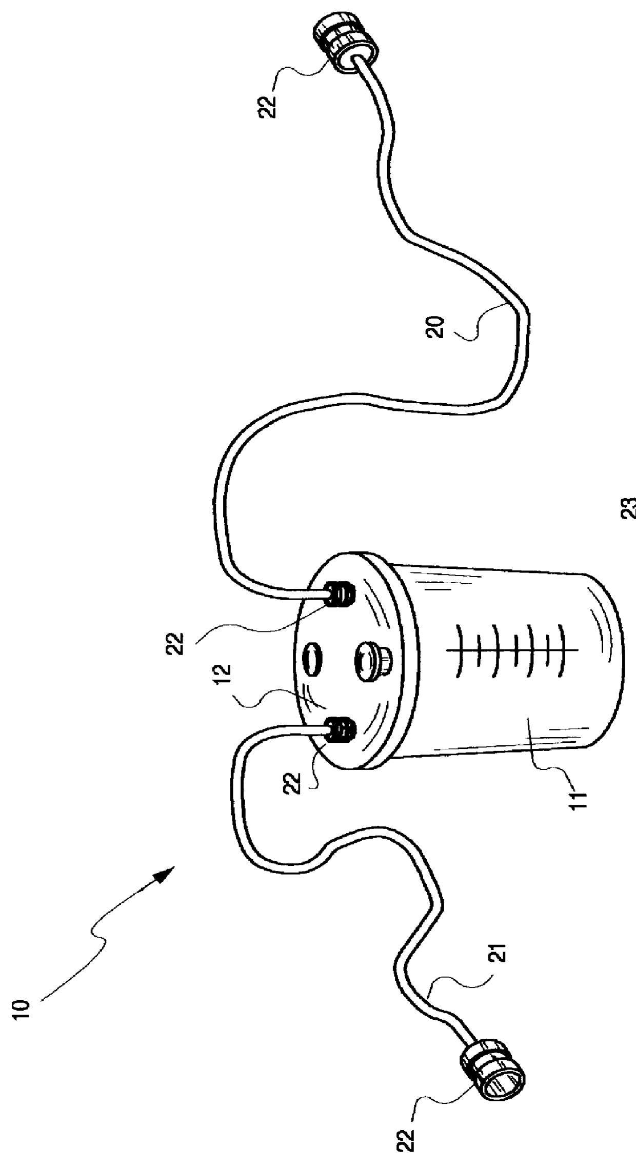
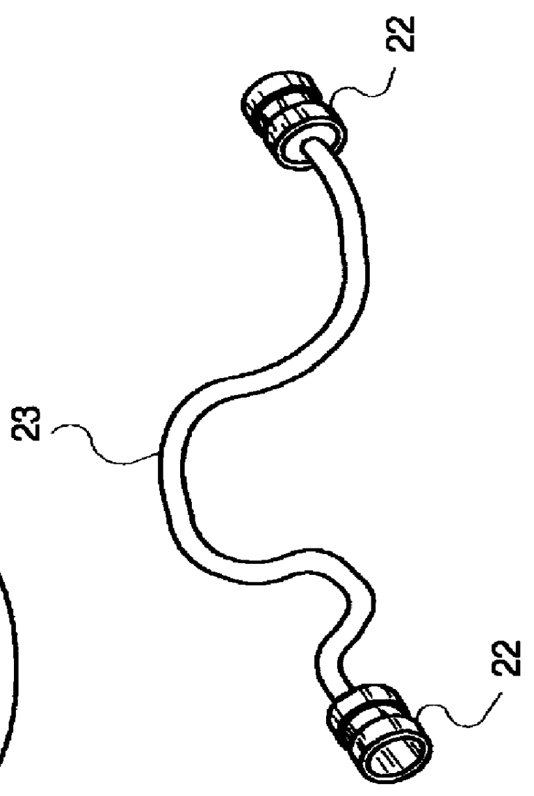
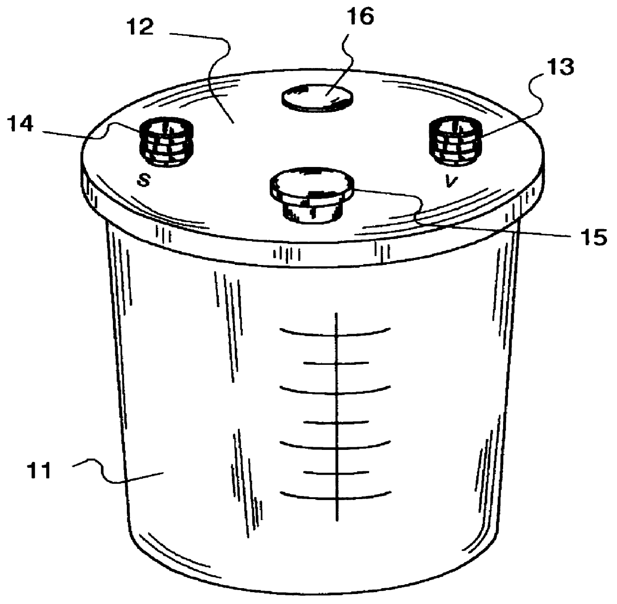
Referring now to FIG. 1, FIG. 2 and FIG. 3, illustrated is a portable, automatic, compressor oil recovery device 10, according to the present invention, wherein a canister 11 is equipped with a lid 12. The canister 111 is generally cylindrical in shape having a disc-shaped base and a side wall extending vertically therefrom, forming a top rim and creating a hollow interior cavity. The lid 12 attaches to the canister 11 via friction fit compression fitting and forms a hermetic seal therewith. The lid 12 includes a vacuum port 13, a suction port 14, a drain plug 15 and a vacuum release plug 16, each of which consists of a conduit providing fluid communication with the interior volume of the canister 11. The vacuum port 13 and suction port 14 include a hose fittings such as a standard 0.25 inch threaded connector. The vacuum port 13 and suction port 14 are labeled with identifying indicia, such as a a "V" and "S," respectively, so as to provide an obvious indication to th...


PUM


Abstract

A compressor oil recovery device for use in removing oil from compressors typically found on condensing units used in air conditioning or refrigeration applications is disclosed. The device consists of a canister with a lid that contains a vacuum port, a suction port, a drain port, and a vacuum release port. A vacuum hose is connected at one end to the vacuum port and at the other end to an electric vacuum pump. A suction hose is connected at one end to the suction port and at the other end to the gauge manifold of a compressor. Upon activating the vacuum pump, a vacuum is created that draws the compressor oil into the canister where it is collected for disposal.

Description

1. Field of the InventionThe present invention relates generally to oil recovery systems and, more particularly, to a portable, automatic, oil recovery system for removing oil from a compressor, of the type typically found in refrigeration or air conditioning units, which is to be repaired or retrofitted with new refrigerant.2. Description of the Related ArtIt is well known that the removal of oil from compressors can be a difficult, time consuming, and many times messy task. The difficulty of this task is increased due to the fact that many compressors do not have a drain port for the removal of oil.In the ancillary art, there are several large oil recovery devices, such as that disclosed in U.S. Pat. No. 5,321,956, issued in the name of Kemp et al. The '956 device discloses a large compressor oil management and separation system, comprising a large main oil storage tank, a pump, valves and remote control means for selectively directing oil from the tank to any one or more of sever...

Claims


Application Information

Patent Timeline
Patent Type & Authority Patents(United States)
IPC IPC(8): F01M11/04F25B45/00
CPCF01M11/045F25B45/00
Inventor GRIFFITH, JR., DAVID R.
Owner GRIFFITH JR DAVID R
Why Eureka
Try Eureka