Device for withdrawing a liquid from a sealed glass ampoule

a technology of glass ampoule and liquid, which is applied in the direction of liquid dispensing, opening closed containers, and preparing samples for investigation, etc., can solve the problems of undesirable, other storage containers suitable for these purposes, and the manipulation involved in handling such liquids in glass ampoules, and achieve the effect of preventing small glass splinters from being sucked

Inactive Publication Date: 2000-08-08
AVL MEDICAL INSTR
View PDF12 Cites 35 Cited by
  • Summary
  • Abstract
  • Description
  • Claims
  • Application Information

AI Technical Summary

Benefits of technology

In order to effectively prevent small glass splinters from being sucked in, a fine-pored filter may be provided at the point or in the lumen of the cannula.

Problems solved by technology

In a number of applications, especially in the instance of quality control or calibration of laboratory equipment by means of quality control liquids or calibrating media, the manipulations involved in handling such liquids contained in glass ampoules, are far from convenient.
Other storage containers suitable for these purposes, however, such as bags or plastic bottles, are undesirable since the gas partial pressures or pH values of the liquids may be subject to changes in the course of prolonged periods of storage, which would render the liquids useless.
Such a device is not suited for automated processes in laboratory equipment, however.
This device is not suited for use with glass vials, however, nor for calibrating media, since the gas injected into the bottle would change the gas partial pressure of the liquid.
It has been found, however, that there is an interaction between the liquid from the ampoule and the ambient air, such that the actual gas partial pressures will deviate from the target values.
The disadvantage of this procedure is its technical complexity and the unfavorable effects of the gas flame on the liquid contents of the ampoule.
The device is not suited for automated withdrawal of the liquid contents of a glass ampoule however.

Method used


Image

  • Device for withdrawing a liquid from a sealed glass ampoule
  • Device for withdrawing a liquid from a sealed glass ampoule
  • Device for withdrawing a liquid from a sealed glass ampoule

Examples


Embodiment Construction

as illustrated by the accompanying drawings, in which

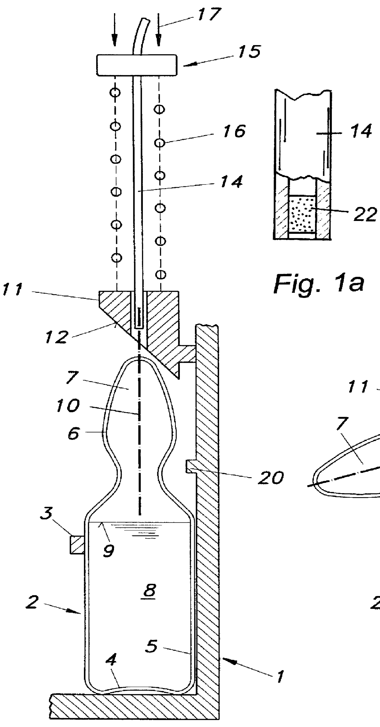
FIG. 1 is an axial section of a device according to the invention, before the withdrawing element is introduced,

FIG. 1a shows a detail of FIG. 1,

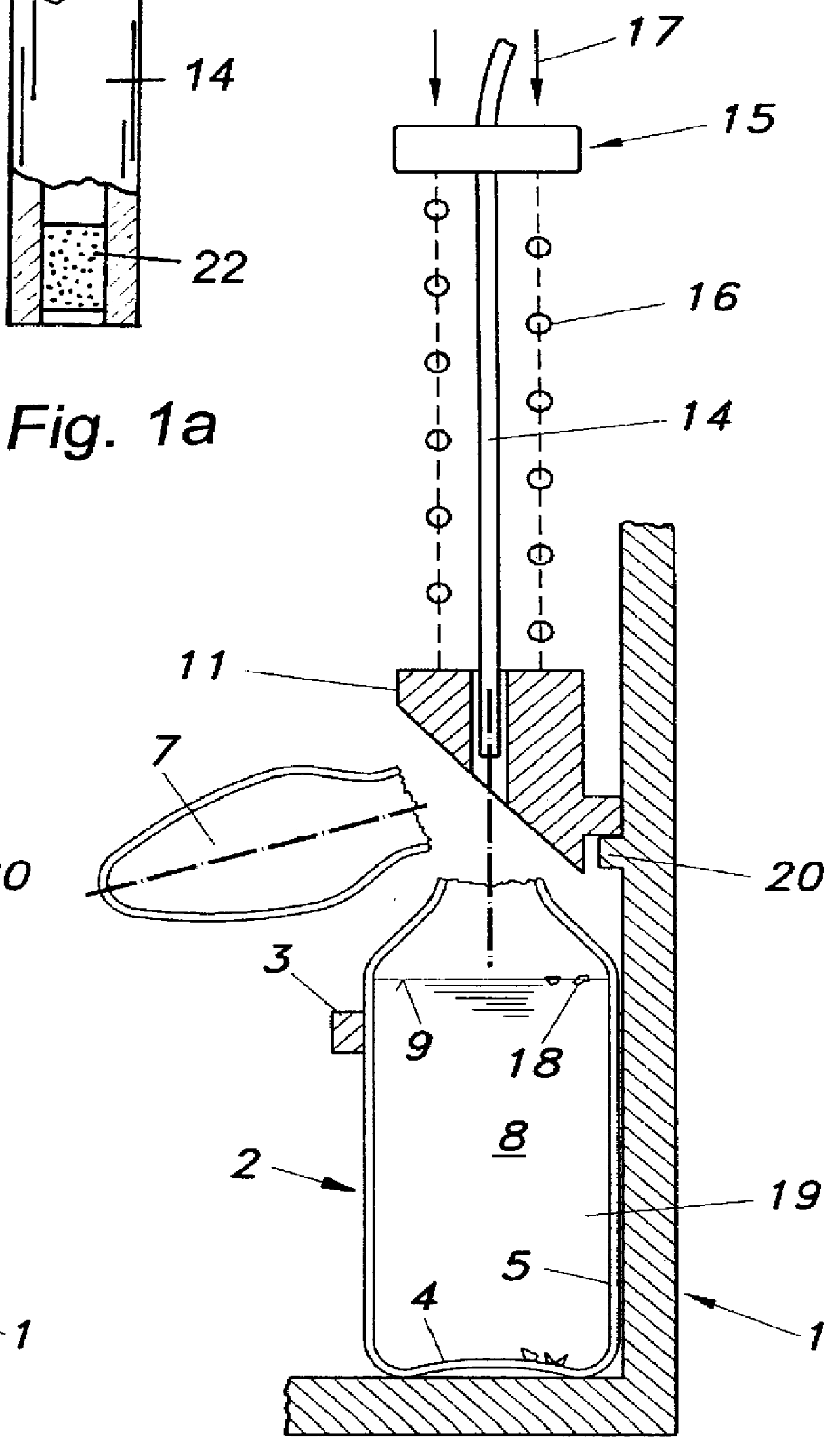
FIG. 2 shows the device of FIG. 1, after the tip of the ampoule has been broken off,

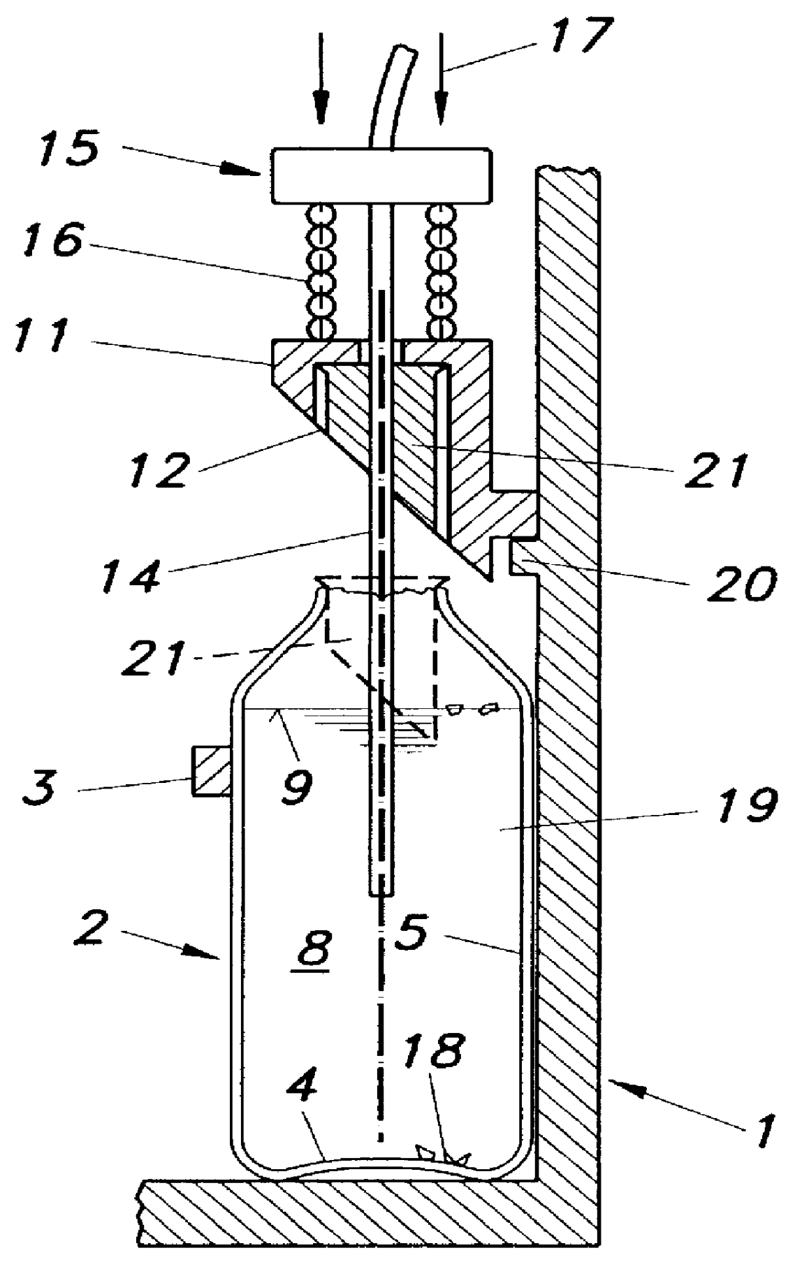
FIG. 3 shows the device of FIG. 1, after the withdrawing element has been introduced into the glass ampoule,

FIG. 4 shows a variant of the device in FIG. 3.

The device shown schematically in FIGS. 1 to 3 is provided with a frame 1, in which a glass ampoule 2 is held, preferably elastically, by a support 3. The glass ampoule 2 includes a bottom 4 shaft 5, neck 6 and tip 7, contains a liquid 8 (calibrating or quality control liquid, or liquid drug) with a surface 9. The glass ampoule 2 is in upright position, its tip 7 pointing upwards, but could also be held in a slightly inclined position, by an alternative frame, provided that the neck and tip regions of the ampoule remain free from the liquid. The device i...


PUM

PropertyMeasurementUnit
forceaaaaaaaaaa
partial pressuresaaaaaaaaaa
pHaaaaaaaaaa

Abstract

A device for withdrawing a liquid from a sealed glass ampoule includes a frame holding the sealed glass ampoule in upright or slightly inclined position, such that a tip of the ampoule points upwardly. An element is provided which will press or knock against the side of the tip or neck of the ampoule in order to break the tip of the ampoule in the region of the neck. The device further includes a withdrawing element which can be introduced into the glass ampoule in an area between the bottom of the ampoule and the surface of the liquid therein, and which includes a cannula for withdrawing the liquid.

Description

The invention relates to a device for withdrawing a liquid from a sealed glass ampoule, including a frame in which the sealed glass ampoule is held in upright or slightly inclined position, the tip of the ampoule pointing upwards.DESCRIPTION OF THE PRIOR ARTIn medical laboratories as well as in doctors' practices and hospitals a large number of glass vials or ampoules are handled, which contain a variety of liquids, such as liquid drugs, or liquids for calibration or quality control. Such ampoules must be opened by hand before use.In a number of applications, especially in the instance of quality control or calibration of laboratory equipment by means of quality control liquids or calibrating media, the manipulations involved in handling such liquids contained in glass ampoules, are far from convenient. Other storage containers suitable for these purposes, however, such as bags or plastic bottles, are undesirable since the gas partial pressures or pH values of the liquids may be sub...

Claims


Application Information

Patent Timeline
Patent Type & Authority Patents(United States)
IPC IPC(8): B67B7/00B67B7/92B67D5/02B67D5/01G01N35/10G01N1/28A61J1/20B67D7/02
CPCB67B7/92B67D7/0277G01N35/10G01N35/1002G01N2001/2893
Inventor RUTHER, HORSTLIST, HELMUTKIRCHMAYER, GERALD
Owner AVL MEDICAL INSTR
Why Eureka
Try Eureka