This helps you quickly interpret patents by identifying the three key elements:
Problems solved by technology
Method used
Benefits of technology
Problems solved by technology
When the contaminants are substantially immiscible with water and are more dense than water, the contaminants tend to sink downward and collect on clay or other impermeable layers.
Old river bed channels or other depressions could therefore be inches away from the point the wellbore is place
Method used
Image
Click on the blue label to locate the original text in one second.
Reading with bidirectional positioning of images and text.
Examples
Example
EXAMPLE
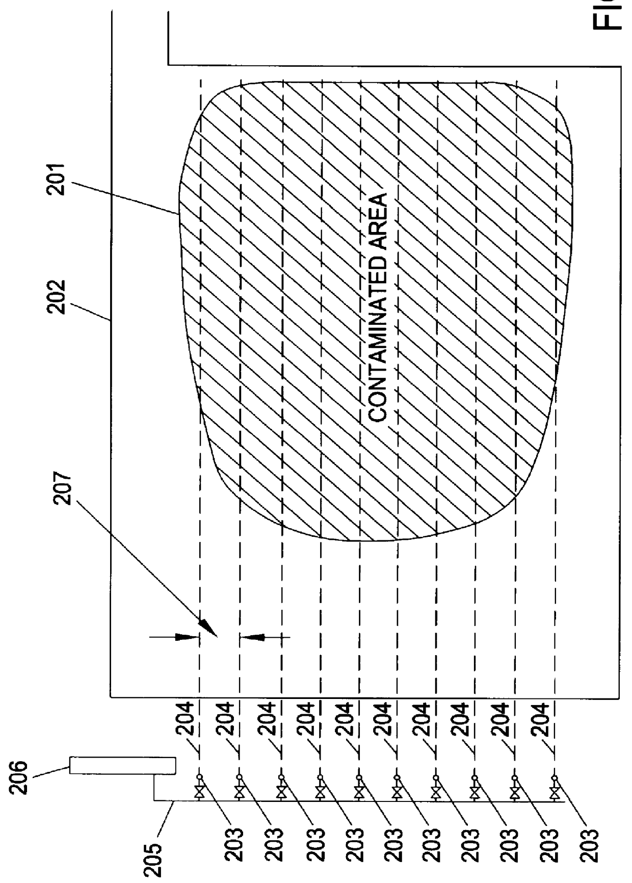
Three alternatives for processes to remove PCBs (exemplary of DNAPLs) from under a water table and lying on a clay layer were evaluated by a numerical simulation using a heat and mass transfer model. The first two alternatives are examples of conventional prior art. The third option is exemplary of a preferred embodiment of present invention. The values used in the simulation are based on an existing contaminated site. The pool of PCBs are 100 feet by 200 feet, and at the deepest point, three feet deep. Pressure-temperature-density relationships of the PCB's at this site were based on data from EPA publications. The model includes a vadose zone, a saturated zone, a free- flowing PCB zone and bounding clay layers underneath. Horizontal wells are placed on top of a bounding clay at the base of the PCB pool, along the length of the pool. The set of 10 wells across 100' of PCB pool give rise to a repetitive pattern 10' wide. The horizontal wells can be drilled and completed in ab...
PUM
Abstract
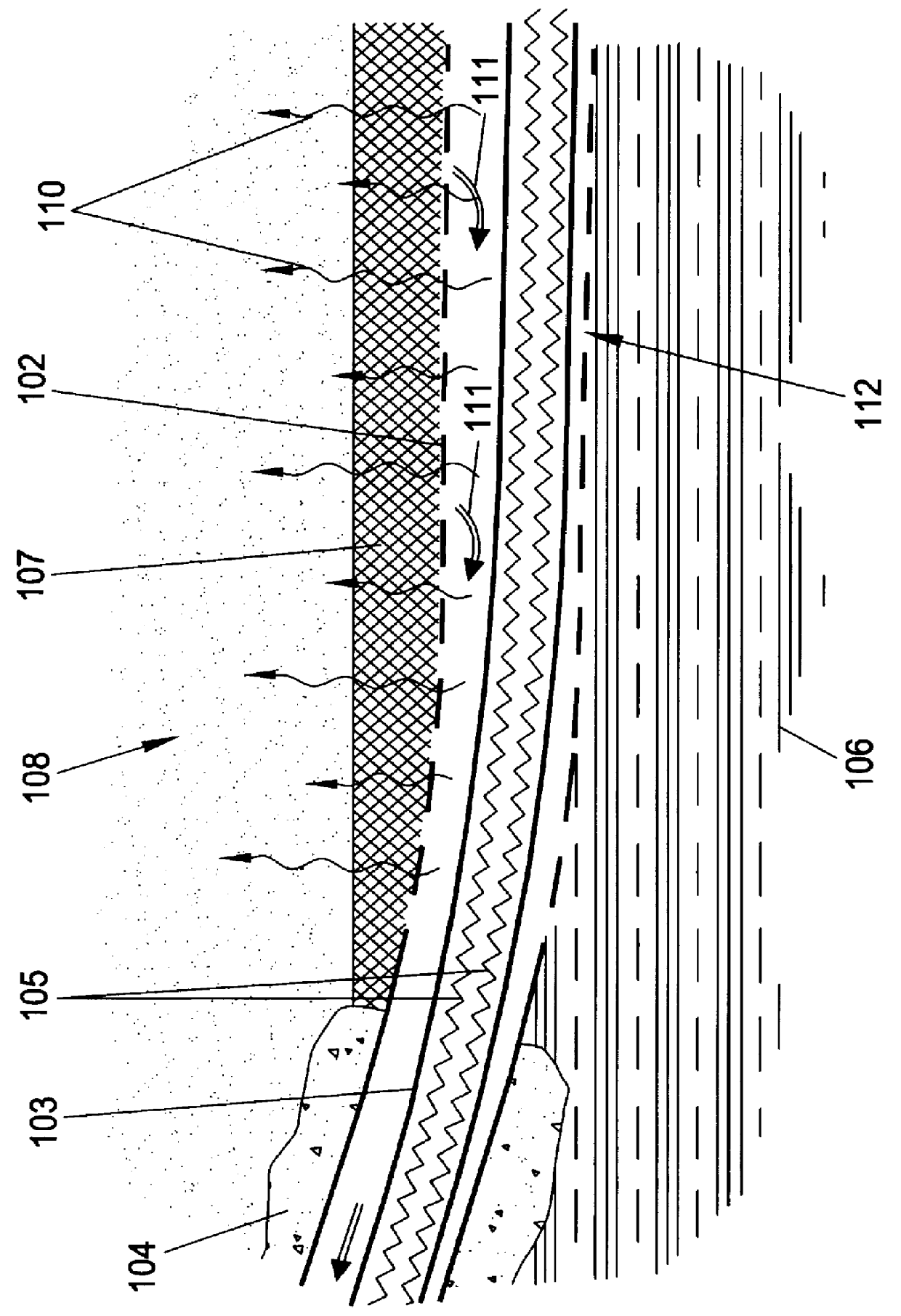
A method is provided to remove contaminants that are more dense than water from a contaminated volume of earth, the contaminants pooled above a layer of earth, the method comprising the steps of: providing an essentially horizontal wellbore along the interface between the layer of earth and the contaminants; heating at least a portion of the contaminants in situ from the wellbore; and removing the heated contaminants by heating through the horizontal wellbore. The wellbores preferably include both heaters and provide a conduit for removal of contaminants, and preferably also provide heaters located within the wellbores in addition to those heaters required to vaporize the contaminants to maintain the contaminants in a vapor state until the vapors reach a well head and can be further processed at the surface.
Description
The invention relates to an in situ thermal desorption process for remediation of denser than water contaminants trapped on impermeable earth layers.BACKGROUND TO THE INVENTIONThermal desorption methods to remove volatile contaminants from soils in situ are suggested in, for example, U.S. Pat. Nos. 4,973,811, 5,076,727, 5,152,341, 5,190,405, 5,193,934, 5,221,827, and 5,271,693. Methods of applying heat include microwave and radio frequency electrical power along with resistance heating between electrodes; injection of hot gases; and conduction of electricity through the soil. Conductive heat transfer from heat injection wells are suggested in, for example, U.S. Pat. Nos. 5,190,405 and 5,271,693. U.S. Pat. No. 5,271,693 suggests a heat injection well through which vapors are extracted from the formation.These methods generally rely on maintenance of a low pressure at the surface or at a vapor extraction wellbore to control movement of contaminants from their initial position to a poi...
Claims
Application Information
Patent Timeline
Application Date:The date an application was filed.
Publication Date:The date a patent or application was officially published.
First Publication Date:The earliest publication date of a patent with the same application number.
Issue Date:Publication date of the patent grant document.
PCT Entry Date:The Entry date of PCT National Phase.
Estimated Expiry Date:The statutory expiry date of a patent right according to the Patent Law, and it is the longest term of protection that the patent right can achieve without the termination of the patent right due to other reasons(Term extension factor has been taken into account ).
Invalid Date:Actual expiry date is based on effective date or publication date of legal transaction data of invalid patent.

