Stackable leg-over-leg ganging chair

a leg-over-leg ganging and seat technology, applied in the field of movable seating, can solve the problem that the design patent does not disclose whether the tubular chair is attached

Inactive Publication Date: 2000-08-22
SHELBY WILLIAMS INDS
View PDF6 Cites 38 Cited by
  • Summary
  • Abstract
  • Description
  • Claims
  • Application Information

AI Technical Summary

Benefits of technology

FIG. 7a is an underneath view of one embodiment of the converging front cross-member and rear cross-member of a ganging chair in accordance with the present invention, illustrating the shorter length of the left side frame member, and an upper bracket of the backrest of the ganging chair;

Problems solved by technology

The design patent does not disclose whether the tubular chair is stackable or connectable in a gang horizontal orientation with like chair structures.

Method used


Image

  • Stackable leg-over-leg ganging chair
  • Stackable leg-over-leg ganging chair
  • Stackable leg-over-leg ganging chair

Examples


Embodiment Construction

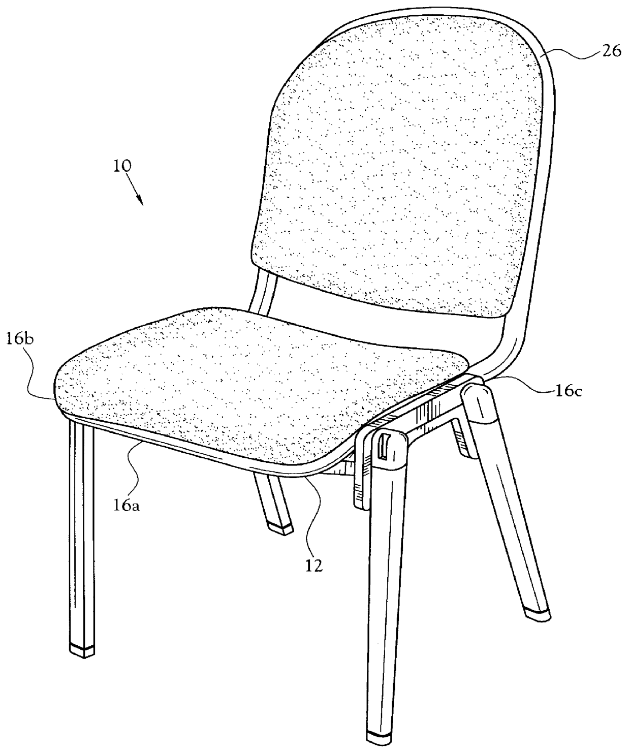
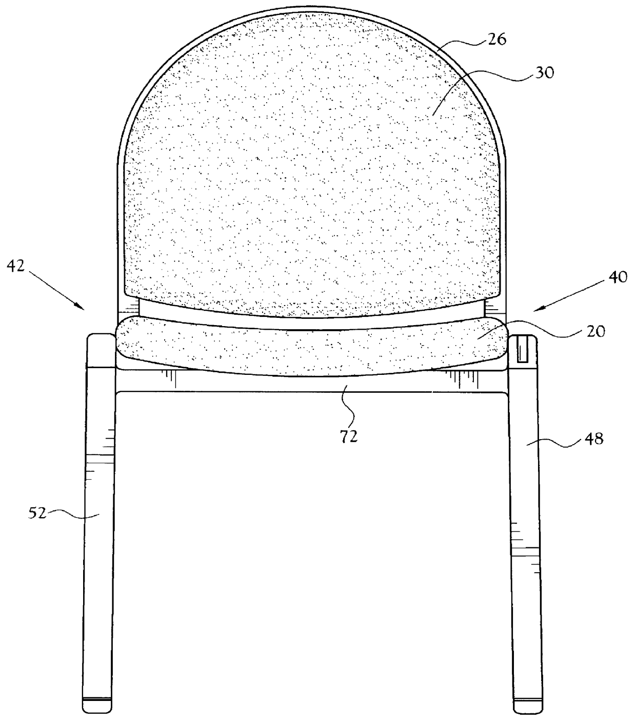
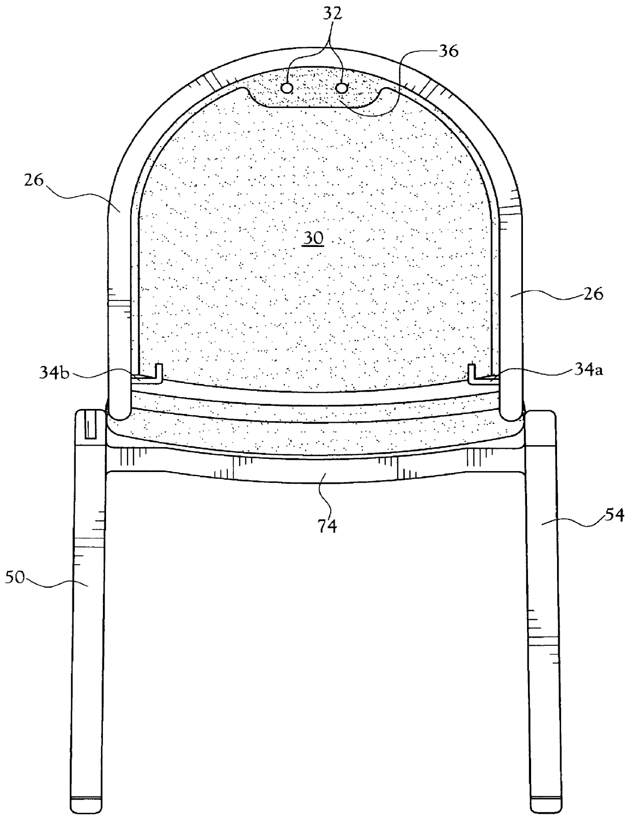
A stachable leg-over-leg ganged chair incorporating various features of the present invention is illustrated generally at 10 in FIGS. 1-12. The stackable chair 10, is designed for vertical stacking (see FIG. 10), and for horizontal side-by-side connecting (see FIGS. 6 and 11), on a supporting surface for the chairs.

From the foregoing description, it will be recognized that the stackable leg-over-leg ganged chair 10 of the present invention offers advantages by providing an attachment mechanism for a plurality of leg-over-leg ganged chairs 10 of like design to be attached side-by-side within less time, with less floor space width for a given number of ganged chairs, and with increased seating capacity for each assembled horizontal row of ganged chairs 10.

One embodiment of the leg-over-leg ganged chair 10 of the present invention includes an upper frame 12 (see FIG. 1), suitably formed of generally cylindrical tubes 14 (see FIG. 7b) that define a generally rectangular upper frame base...


PUM


Abstract

A vertical stacking leg-over-leg ganged chair is attachable side-by-side and includes an upper frame adapted to receive and support a seating platform, and a lower frame supporting the upper frame, and a backrest for supporting a user seated in the chair. The ganged chair includes a front pair of legs angled frontward, and a rear pair of legs angled rearward, each pair connected underneath the lower frame. The right legs are connected to a right frame member, and the left legs to a left frame member, with the left frame member being of a lesser length than the right frame member. In a side-by-side ganged setup, the wider spaced apart right legs of one ganged chair fit over the left legs of a second like chair, forming a single width leg unit on either side of the ganged chairs. Each upper portion of the left legs includes an elongated slot that accepts an elongated lug on the upper portion of each right leg, for connective support when chairs are attached horizontally. The configuration of legs, the angles of the legs, and the rearward angle of the backrest, allow the ganged chair to be stacked vertically for ease of transfer. The leg-over-leg structure allows connection side-to-side, providing a lesser overall width of chairs when in the ganged configuration.

Description

The present invention relates generally to the field of movable seating, and more particularly to chairs that are stackable during storage, and are connectable side-to-side during use.BACKGROUND OF INVENTIONIn the field of movable seating, chair structures may be designed to be attached side-to-side during use, and may be stackable for storage. It is a preference in the field that the chair structures be easily connectable and disconnectable in side-by-side relationships (i.e. ganged), and the chair structures be stackable when disconnected for ease of movement from one location to another for use, and for storage.Typical of the art are those devices disclosed in the following U.S. Patents. In U.S. Pat. No. 3,827,749, to Johnson et al., a chair structure is disclosed that may be stacked vertically, and may be connectable side-by-side, with a right-side leg member of a first chair resting below and in contact with a left-side leg member of a second chair. The left side leg of each ch...

Claims


Application Information

Patent Timeline
Patent Type & Authority Patents(United States)
IPC IPC(8): A47C1/00A47C1/124A47C3/04A47C3/00
CPCA47C1/124A47C3/04
Inventor CARUSO, JEROME C.CARUSO, STEVEN J.
Owner SHELBY WILLIAMS INDS
Why Eureka
Try Eureka