Energizing circuit for EAS marker deactivation device

a technology of deactivation device and eas marker, which is applied in the direction of burglar alarm mechanical actuation, burglar alarm by hand-portable object removal, instruments, etc., can solve the problems of false alarm, failure to deactivate the marker, and the maximum speed at which the marker can be deactivated, etc., to achieve high throughput, easy to use, and operate reliably

Inactive Publication Date: 2000-08-29
TYCO FIRE & SECURITY GMBH
View PDF12 Cites 30 Cited by
  • Summary
  • Abstract
  • Description
  • Claims
  • Application Information

AI Technical Summary

Benefits of technology

It is a further object of the invention to provide an energizing circuit which makes the deactivation device easy to use.
It is still another object of the invention to provide an EAS marker deactivation device which operates reliably and with high throughput.

Problems solved by technology

One challenge faced in designing marker deactivation devices is the need to provide reliable deactivation of a marker regardless of the orientation of the marker at the time that the marker is presented for deactivation.
A limiting factor in terms of throughput is the maximum speed at which markers can be swept over the deactivation device while still providing reliable deactivation.
Another problem encountered in prior art marker deactivation devices relates to a detection circuit included in the deactivation device to detect the marker and then trigger generation of the deactivation signal field.
As a result, the marker may be detected by detection equipment at a store exit, thereby causing a false alarm.
Again, the outcome in such a case is a failure to deactivate the marker, and a potential false alarm at the store exit.

Method used


Image

  • Energizing circuit for EAS marker deactivation device
  • Energizing circuit for EAS marker deactivation device
  • Energizing circuit for EAS marker deactivation device

Examples


Embodiment Construction

A preferred embodiment of the invention will now be described, initially with reference to FIGS. 1-3.

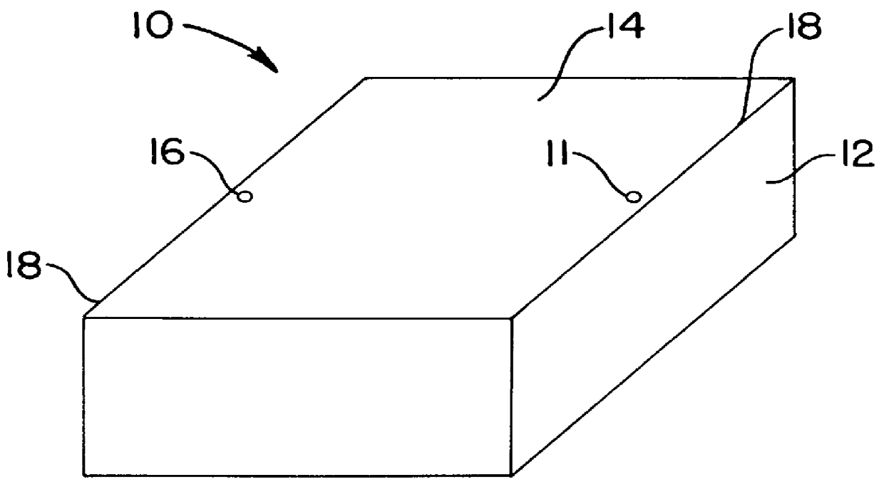
FIG. 1 shows the exterior of a deactivation device 10 provided in accordance with the invention. The device 10 includes a housing 12, which may be formed of molded plastic. The housing 12 has a substantially square top surface 14 over which EAS markers (not shown) may be swept for deactivation. Installed on the top surface 14 are optical sensors 16. As shown in FIG. 1, the number of optical sensors is two, and each sensor is installed adjacent to a central portion of a respective one of a pair of opposed edges 18 of the top surface 14.

The housing 12 contains electrical components of the deactivation device 10, as will be described below. As will be seen, the optical sensors 16 are provided to trigger operation of the deactivation device 10.

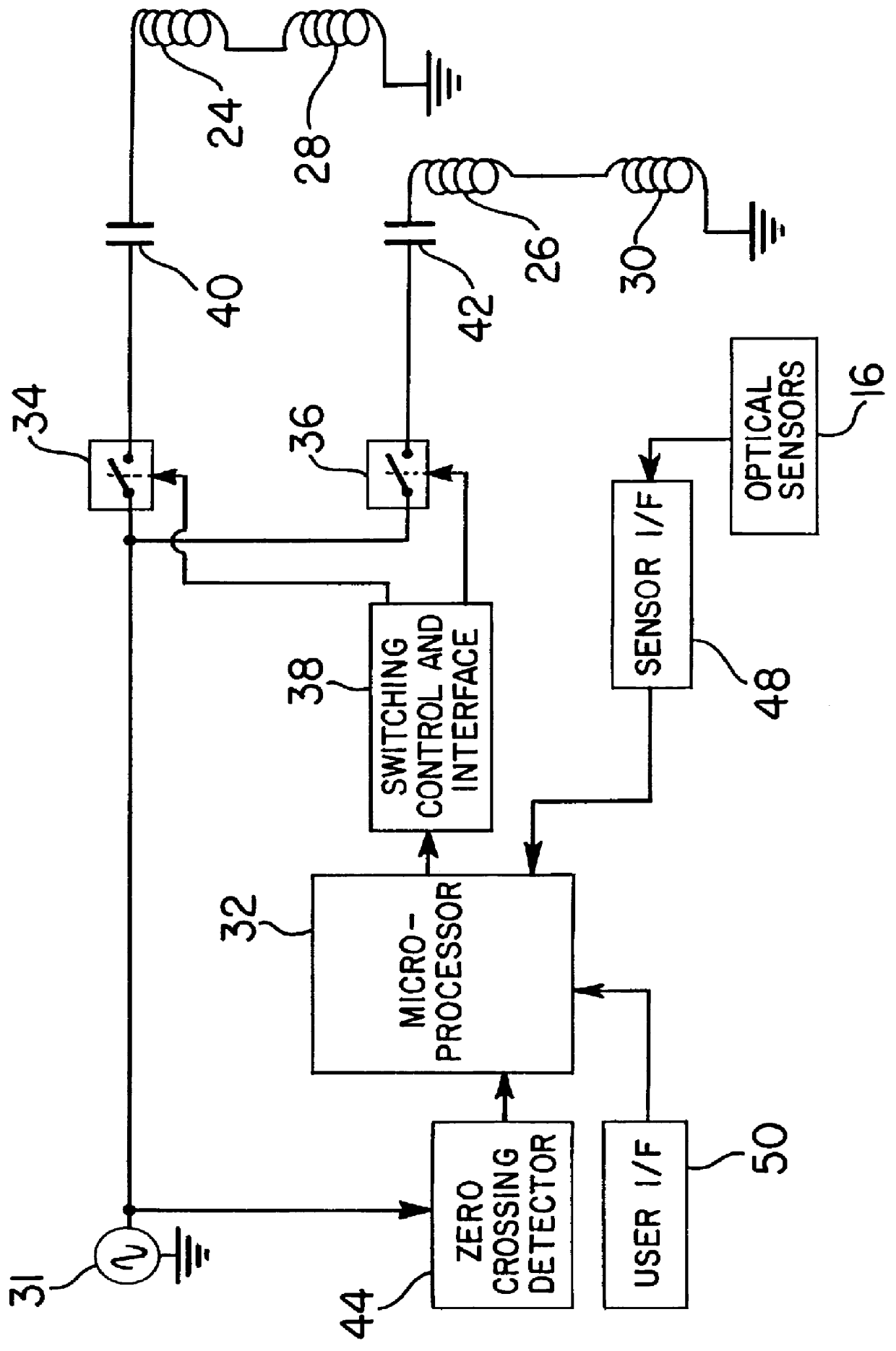
FIG. 2 shows, in the form of a block diagram, the electrical components of the deactivation device 10. In one preferred embodiment, four coils 24,...


PUM


Abstract

A device for deactivating a magnetomechanical EAS marker includes two coils and an energizing circuit for alternately driving the coils. One coil is driven for one cycle of an alternating power signal, and then the other coil is driven for one cycle, and this sequence is repeated. The driving signal is switched from one coil to the other at a point in time which corresponds to a zero crossing of the current level of the driving signal.

Description

This invention relates generally to electronic article surveillance (EAS) and pertains more particularly to so-called "deactivators" for rendering EAS markers inactive.It has been customary in the electronic article surveillance industry to apply EAS markers to articles of merchandise. Detection equipment is positioned at store exits to detect attempts to remove active markers from the store premises, and to generate an alarm in such cases. When a customer presents an article for payment at a checkout counter, a checkout clerk either removes the marker from the article, or deactivates the marker by using a deactivation device provided to deactivate the marker.Known deactivation devices include one or more coils that are energizable to generate a magnetic field of sufficient amplitude to render the marker inactive. One well known type of marker (disclosed in U.S. Pat. No. 4,510,489) is known as a "magnetomechanical" marker. Magnetomechanical markers include an active element and a bi...

Claims


Application Information

Patent Timeline
Patent Type & Authority Patents(United States)
IPC IPC(8): G08B13/24G06K17/00G08B13/14
CPCG08B13/2402G08B13/2411G08B13/242
Inventor ALICOT, JORGE FERNANDONARLOW, DOUGLAS A.COPELAND, RICHARD L.LAMBETH, DAVID N.
Owner TYCO FIRE & SECURITY GMBH
Why Eureka
Try Eureka