Flow-down ice maker

a flow-down ice maker and flow-down technology, which is applied in the direction of ice production, domestic cooling devices, lighting and heating devices, etc., can solve the problems of small differences and achieve the effect of relatively accurate setting

Inactive Publication Date: 2000-09-05
HOSHIZAKI ELECTRIC CO LTD
View PDF6 Cites 16 Cited by
  • Summary
  • Abstract
  • Description
  • Claims
  • Application Information

AI Technical Summary

Benefits of technology

The present invention maims to solve the above problems inherent in the conventional technique. An object of the present invention is to provide a flow-down ice maker which is capable of detecting the ice-making water level or allowing the ice-making water level to be set relatively accurately even if the surface of the ice-making water is inclined relative to the apparatus.

Problems solved by technology

However, in practice this difference will not be great.

Method used


Image

  • Flow-down ice maker
  • Flow-down ice maker
  • Flow-down ice maker

Examples


Embodiment Construction

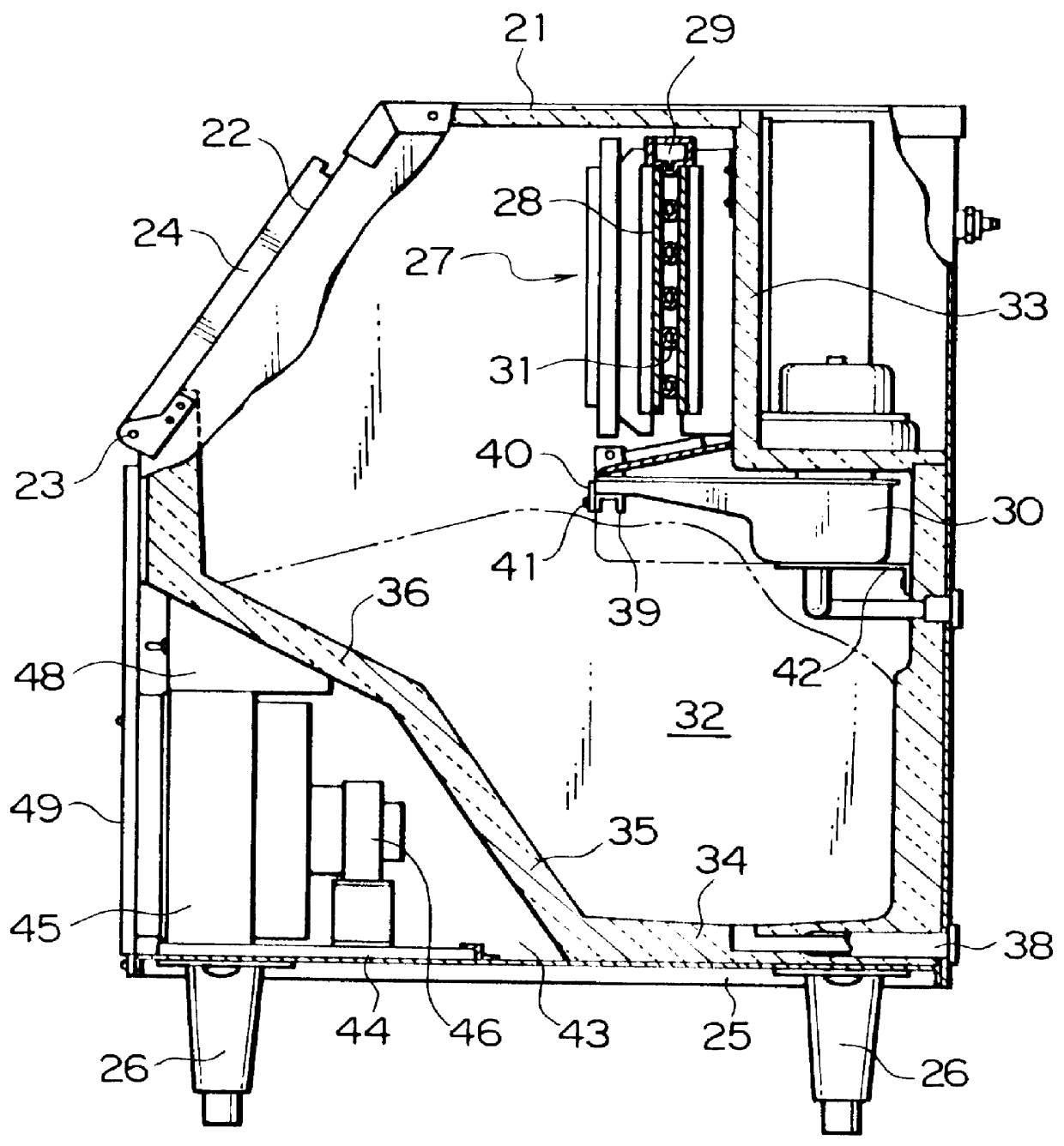
A preferred embodiment of the present invention will now be explained using the attached drawings. FIG. 1 is a cross-section of a side elevation of a flow-down ice maker according to an embodiment of the present invention. The external case 21 is a stainless steel box which is provided with an opening port 22 for taking-out ice formed in the upper front portion thereof. The opening port 22 for taking-out ice is closably sealed by a lid 24 which is rotatably attached to the external case by means of metal hinges 23. The external case 21 is provided with a rectangular base plate 25, and a plurality of support legs 26 are disposed on the underside of the base plate 25.

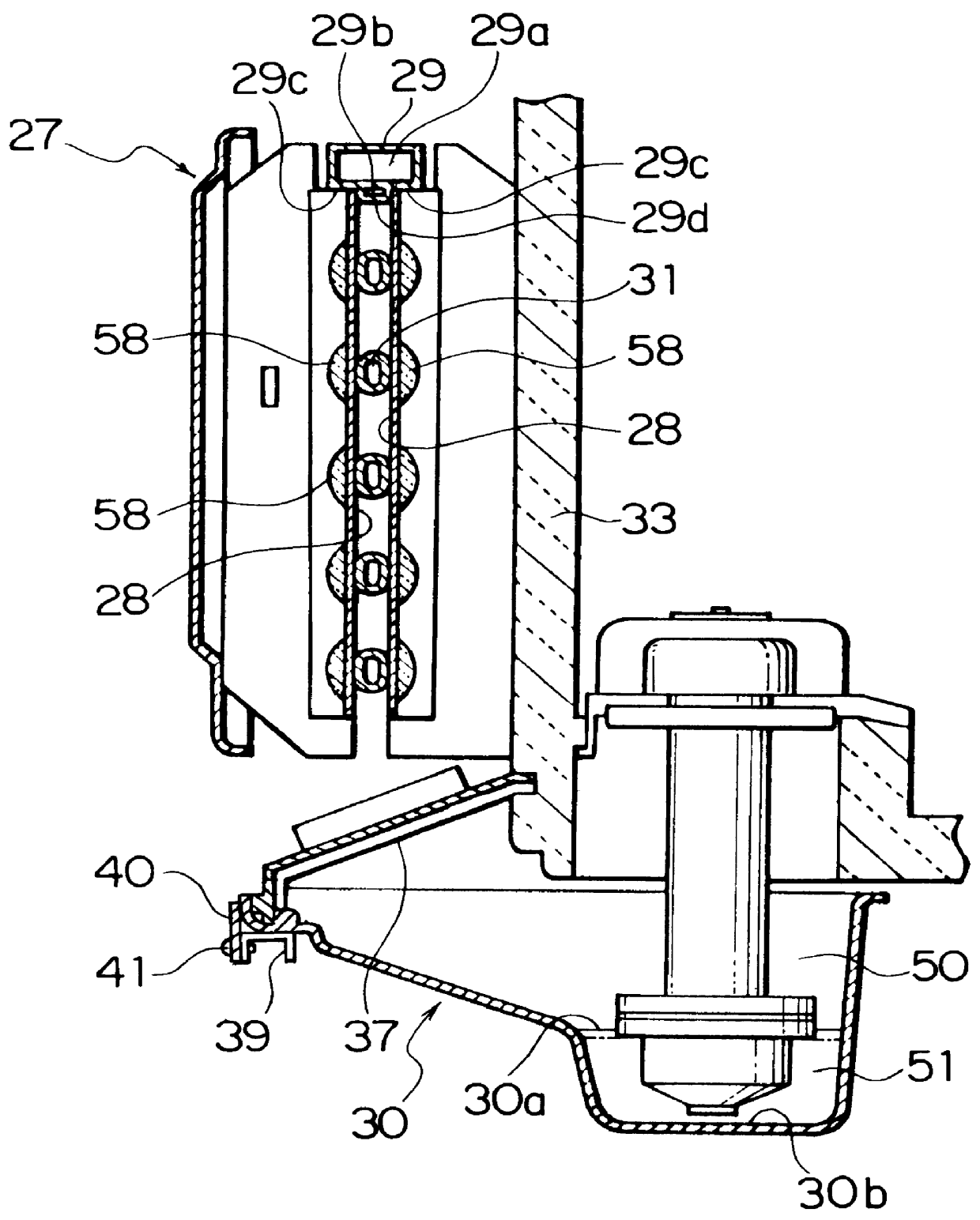
An ice-making portion component 27 is disposed in the upper portion within the external case 21. As shown in FIG. 2, the ice-making portion component 27 comprises: a pair of front and back ice-making plates 28; and a sprinkler 29, which is disposed at the top of these ice-making plates 28. The sprinkler 29 comprises: an i...


PUM


Abstract

An ice-making water tank 30, which has a main body 50, is disposed generally below ice-making plates 28. A deep portion 51 of smaller cross-section is formed in the main body 50. The discharge inlet 56 of an overflow pipe 55 is disposed in the central portion of the water surface in the main body 50, and the height of the discharge outlet is set at the upper limit H of the level of the ice-making water. A float switch 57, which sets the lower limit of the water level, is disposed in the central portion of the water surface in the deep portion. Thus, water levels which are almost equal to the prescribed upper limit H and lower limit L can be set even if the ice-making water tank is mounted at an inclined angle.

Description

BACKGROUND OF THE INVENTION1. Field of the InventionThe present invention relates to a flow-down ice maker which produces ice by causing ice-making water to flow over an ice-making plate and cooling the ice-making water by means of an evaporator.2. Description of the Related ArtFIG. 5 is a diagram showing the internal construction of the conventional flow-down ice maker disclosed in Utility Model No. 60-33182. An ice-making plate 3, over the front surface of which ice-making water flows and to the back surface of which an evaporator 2 is attached, is disposed at an inclined angle within a housing 1 composed of heat-insulating material. A sprinkler 4 is disposed along the top edge of the ice-making plate 3. An ice-making water tank 5 is disposed below the ice-making plate 3. The ice-making water tank 5 is shaped such that its lateral surface area decreases continuously towards the bottom (i.e., the tank is narrower at the bottom than at the top). Ice-making water is supplied to the i...

Claims


Application Information

Patent Timeline
Patent Type & Authority Patents(United States)
IPC IPC(8): F25C1/12F25C1/22
CPCF25C1/12F25C2400/14F25C2700/04
Inventor KATO, SONOOYAMADA, HATSUOSAKAI, TADASHISTEWARD, DOUGLAS TROY
Owner HOSHIZAKI ELECTRIC CO LTD
Why Eureka
Try Eureka