
Microfilm search device and method
a microfilm and search device technology, applied in the field of microfilm search devices, can solve the problems of inability to accurately determine the presence of frames, inability to reduce the diameter of optical fibers, and inability to infinitely reduce the length of frames,
- Summary
- Abstract
- Description
- Claims
- Application Information
AI Technical Summary
Problems solved by technology
Method used
Image

Examples
Embodiment Construction
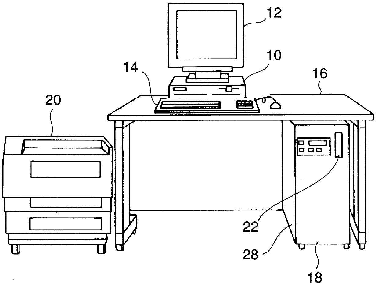
In FIG. 1, a reference numeral 10 denotes a computer body containing a CPU or other processing means. Display means 12 such as a CRT or a liquid crystal panel, and a keyboard 14 are placed on a desk 16. A scanner 18 is stored under the desk 16 and incorporates therein a microfilm search device according to the present invention. Numeral 20 denotes a printer placed beside the desk 16.
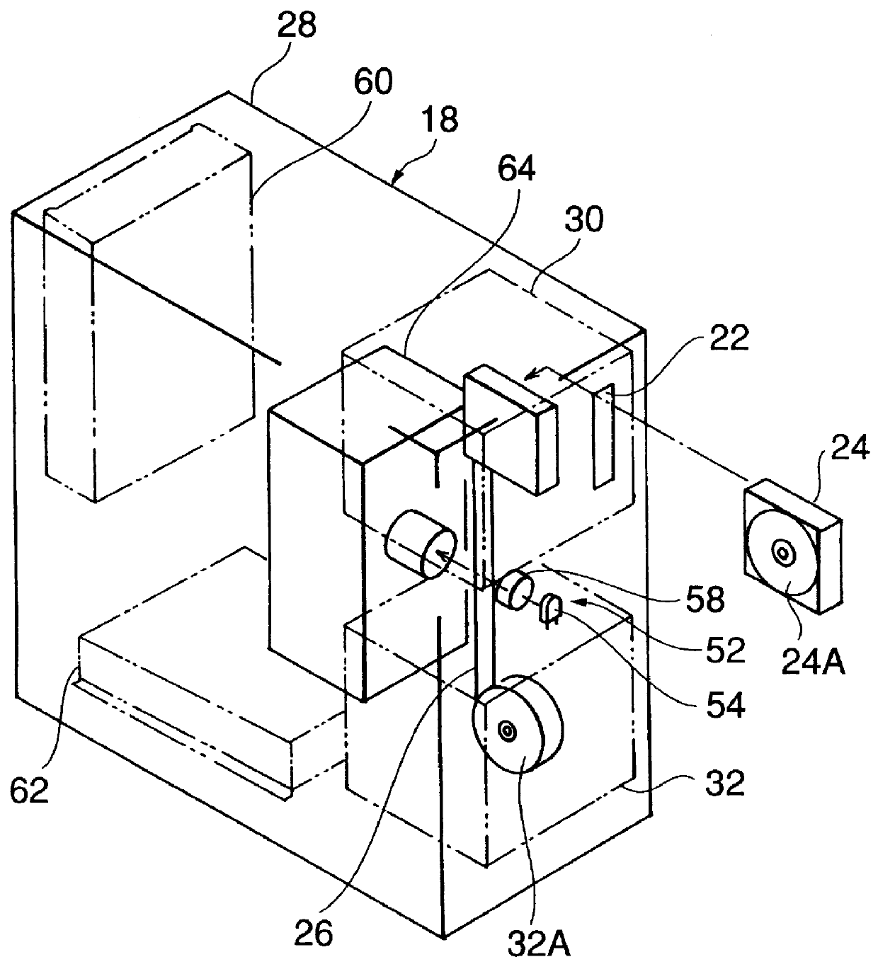
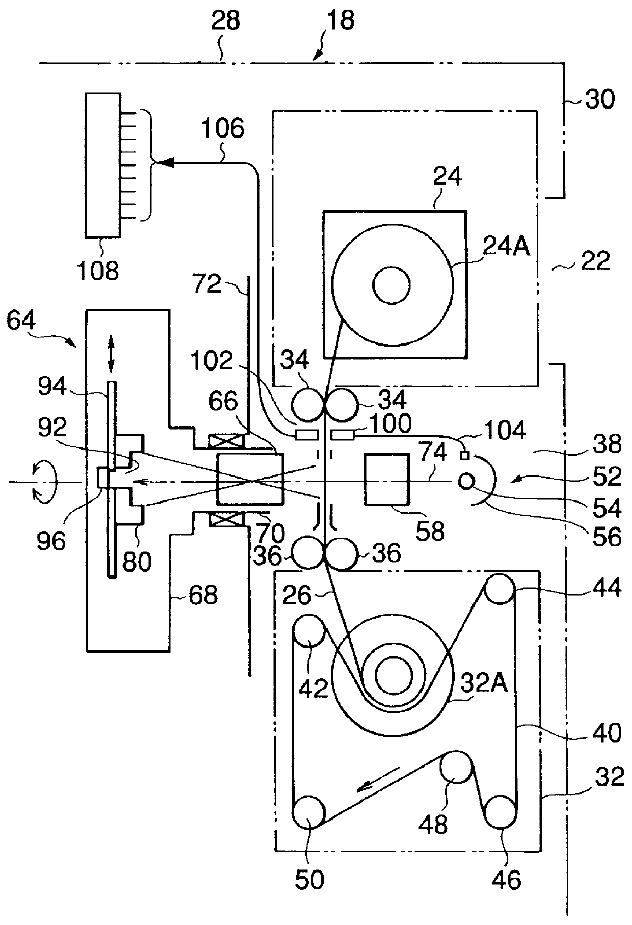
The scanner 18 has a cartridge insertion port 22 formed in the upper portion of its front panel. The scanner 18 reads, at a low resolution, an image on a roll of microfilm 26 with a width of 16 mm held in a cartridge 24 (refer to FIGS. 2 and 3) which is loaded through the insertion port 22. The CPU in the computer body 10 performs a predetermined image processing of the read image, and the resultant image is displayed on the display means 12.
The reading or scanning operation of the image is carried out while the roll film 26 moves without moving a line sensor 96, which will be described hereinafter in de...
PUM
 Abstract
Description
Claims
Application Information