Energy conserving counter using terminal count value and method therefor

a technology of energy conserving counter and terminal count value, which is applied in the direction of pulse technique, process and machine control, instruments, etc., can solve the problem of negligible differen

Inactive Publication Date: 2000-09-05
ST CLAIR INTPROP CONSULTANTS
View PDF2 Cites 5 Cited by
  • Summary
  • Abstract
  • Description
  • Claims
  • Application Information

AI Technical Summary

Problems solved by technology

However, even in this worst case situation the difference

Method used


Image

  • Energy conserving counter using terminal count value and method therefor
  • Energy conserving counter using terminal count value and method therefor
  • Energy conserving counter using terminal count value and method therefor

Examples


first embodiment

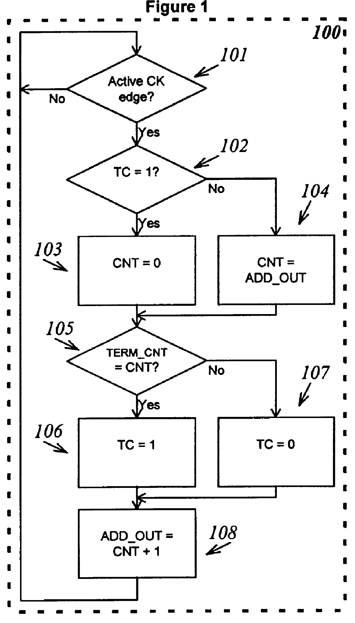
We first describe one embodiment of the inventive method, then describe exemplary structures which may be used to implement the invention and describe additional embodiments of the inventive method relative to the structures. In a first embodiment, a method for counting a predetermined number of counts is provided. A count end value is identified which is greater than or equal to (not less than) the predetermined number of counts. The count end value is chosen such that it is representable by n symbols (designated n-1, n-2, . . . , m, m-1, . . . , 1, 0) where the most significant n-1 through m symbols are a first binary symbol and the least significant m-1 through 0 symbols are a different second binary symbol, for example "1" and "0". An n-symbol current count value (also representable by n-1, n-2, . . . , m, m-1, . . . , 1, 0 symbols) is initialized to a count start value which is equal to the count end value minus the predetermined number of counts, then as the counter counts, th...

embodiment 30

There is one other important difference between conventional counting structure 10 and method 100 and the inventive counting structure (See, for example counter embodiment 30 in FIG. 7) method 400. Counter 10, constructed to perform method 100, may be used to count all values of TERM.sub.-- CNT with substantially the same utility so long as there are a sufficient number of bits to represent the desired TERM.sub.-- CNT. By comparison, a counter constructed to execute the inventive method 400, although still working correctly for all values of TERM.sub.-- CNT, may not be the most suitable choice for a counting structure or method in all situations. For example, when all bits of TERM.sub.-- CNT are "1", or when TERM.sub.-- CNT is fixed at a value equal to NCEV, where NCEV is found according to steps in the procedure shown and described below, then the inventive counter structure and method may loose some of the advantages over the conventional structure and method.

The new count end val...

example 1

Terminal Count Shifted From 136 to 192

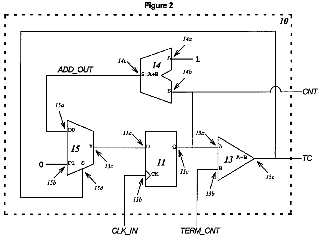
TERM.sub.-- CNT in this example is 136, or 10001000 in binary. The third and seventh bits (starting with bit number 0, e.g. TERM.sub.-- CNT[0]) of TERM.sub.-- CNT, that is TERM.sub.-- CNT[7] and TERM.sub.-- CNT[3], are both 1. In conventional counter 10, because the terminal count value is fixed, a two-input AND gate connected to CNT[3] and CNT[7] is adequate as the comparator 13. Typically an AND gate consumes no power until its output toggles, thus P.sub.13 in counter 10 in this case is nearly 0.

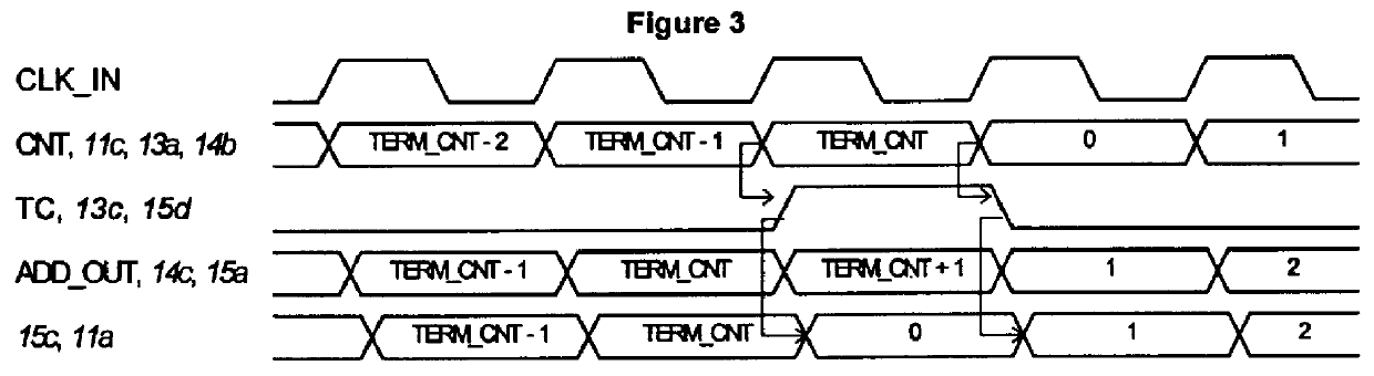
In the inventive counter 30, the count start value is shifted from 0 to 56, and the count end value is shifted from 136 to 192 (11000000 in binary). The same two-input AND gate is used as the comparator 33, but the bit to check is moved from CNT[3] to CNT[6]. Even though this change only moves some capacitance to a different signal, the toggle rate associated with the capacitance is reduced from 18 toggles down to 4 toggles, a reduction of about 4.5 ti...


PUM


Abstract

Structure and method for counting a predetermined number of counts is provided. A count end value is identified which is greater than or equal to (not less than) the predetermined number of counts. The count end value is chosen such that it is representable by n symbols (designated n-1, n-2, . . . , m, m-1, . . . , 1, 0) where the most significant n-1 through m symbols are a first binary symbol and the least significant m-1 through 0 symbols are a different second binary symbol, for example "1"0 and "0". An n-symbol current count value (also representable by n-1, n-2, . . . , m, m-1, . . . , 1, 0 symbols) is initialized to a count start value which is equal to the count end value minus the predetermined number of counts, then as the counter counts, the current count value is incremented by one (or some other count increment) for each count or cycle of the counter. After each iteration (or before the next iteration of the counter cycle) each of the n-1, . . . , m symbols are compared with the first binary symbol. If the n-1, . . . , m symbols match, a count completed indicator is generated signifying that the desired count has been reached. Due to the manner in which the count values are chosen, it is not necessary to examine or compare the other m-1, . . . , 0 symbols. A counter structure, including an electronic counter, a mechanical counter, and a method for designing a counter are also provided.

Description

This invention pertains generally to the field of digital counter circuits and more particularly to the field of fast digital counter circuits having a reduced number of gates and low power consumption.Counters are conventionally used in virtually every digital circuit design and implementation. In such conventional counter circuits, when the counter count reaches a target value, a terminal count output is typically generated. This terminal count output is then used to trigger other events in the digital circuit.We now identify certain notational conventions that will be used to describe conventional counter structure and method as well as the inventive counter structure and method in subsequent sections of this disclosure. For an n-bit wide signal or signal value, the most significant bit is the bit designated as bit (n-1), and the least significant bit is the bit designated bit 0. We note that in general, a signal can have different values at different times. The term "name [index...

Claims


Application Information

Patent Timeline
IPC IPC(8): G06F7/02H03K23/66H03K21/38H03K21/00H03K23/00
CPCG06F7/026H03K21/38H03K23/66
Inventor LIAO, WILLIAM
Owner ST CLAIR INTPROP CONSULTANTS
Why Eureka
Try Eureka