Measuring device and method for contactless determining of the 3-dimensional form of a peripheral groove in a spectacle frame

a technology of measuring device and peripheral groove, which is applied in the field of ophthalmic optics, can solve the problems of further inaccuracy in measurement, cracking or breaking of glass, and inability to furnish data on the entire three-dimensional geometry

Inactive Publication Date: 2000-09-19
FRAUNHOFER GESELLSCHAFT ZUR FOERDERUNG DER ANGEWANDTEN FORSCHUNG EV
View PDF3 Cites 58 Cited by
  • Summary
  • Abstract
  • Description
  • Claims
  • Application Information

AI Technical Summary

Problems solved by technology

Variations in shape between the precise course of the frame groove and the glass facet of the spectacle lens provoke, however, strain in the spectacle lens, which may easily result in a crack or break of the glass.
The subject matter of the German Patent 41 31 331 moreover entails the disadvantage that the sensing device for sensing the contour by direct mechanical contact requires a holder for the spectacle frame, which clamps the frame in opposition to the force produced thereon by the sensing device.
As a result, the clamping device as such as well as the sensing pin may deform the spectacle frame component, which results in a further inaccuracy in measurement.
Furthermore, the tactile measuring devices present the disadvantage that they have been designed only for the detection of the rough course of the frame groove and that they are not suitable to furnish data on the entire three-dimensional geometry of both the frame component as such and the other components of the spectacle frame.
What is problematic is the correct recording of the spectacle shape.
The devices so far developed are not suitable and in a position to detect the entire spectrum of spectacle shapes.
With the device described in the laid-open

Method used


Image

  • Measuring device and method for contactless determining of the 3-dimensional form of a peripheral groove in a spectacle frame
  • Measuring device and method for contactless determining of the 3-dimensional form of a peripheral groove in a spectacle frame
  • Measuring device and method for contactless determining of the 3-dimensional form of a peripheral groove in a spectacle frame

Examples


Embodiment Construction

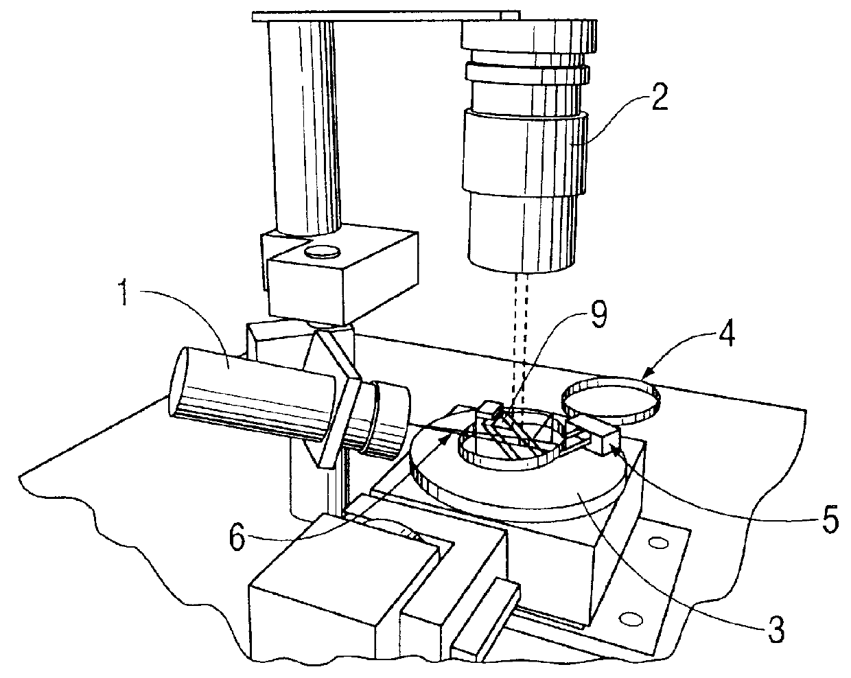
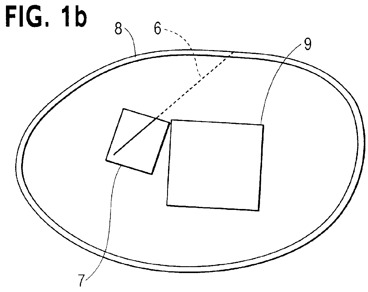
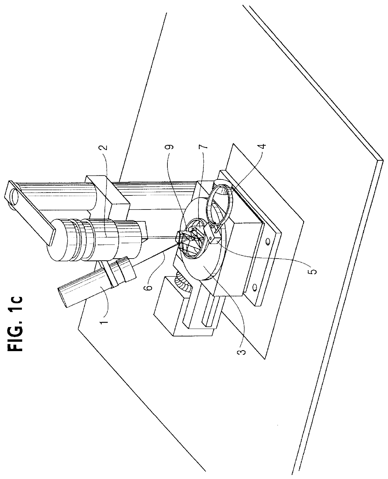
FIG. 1a illustrates an expedient embodiment of an inventive measuring system comprising a source of light 1, a detector unit 2 as well as a holding device 3 configured as turntable. A spectacle frame 4 is mounted on the holding device 3 by means of a fixing device 5 such that the inside of the spectacle groove is freely accessible for the light beam 6. In the embodiment illustrated here, the light source 1, which is designed as a laser, is disposed at an angle relative to the opening of the spectacle frame, so that the light beam 6 will be incident directly on the inside of the groove of the spectacle frame 4 with oblique incidence. Other arrangements of the light source 1 are, of course, conceivable as well. In accordance with FIG. 1b, for instance, the light beam 6 may be initially adjusted to be incident on an optical deflector system 7 which deflects the beam to the spectacle frame groove 8. A separate imaging system 9 deflects the light reflected or scattered by the groove to a...


PUM


Abstract

PCT No. PCT/DE98/00713 Sec. 371 Date Dec. 22, 1999 Sec. 102(e) Date Dec. 22, 1999 PCT Filed Mar. 10, 1998 PCT Pub. No. WO98/45664 PCT Pub. Date Oct. 15, 1998What is described here is a measuring system for the non-contacting detection of the three-dimensional shape of a groove peripherally extending in a spectacle frame, comprising a light source directing its light beam onto the groove or having its beam deflected thereon by means of an optical deflector system, an optical imaging system which projects the light reflected at the groove onto an optical detector unit and which is disposed in a centered position relative to the groove to be measured on the spectacle frame, a holding means supporting the spectacle frame, which is supported for rotation relative to the light source, the detector system and the optical imaging system about a centering axis of a surface inscribed by the peripheral groove of the spectacle frame, as well as an evaluation unit for determining the three-dimensional shape of the groove, which operates in correspondence with the triangulation principle. Moreover, an appertaining method is proposed.

Description

The invention relates to a measuring system for the non-contacting detection of the three-dimensional shape of a groove peripherally extending in a spectacle frame, comprising a light whose directing its light beam onto the groove, an optical imaging system which projects the light reflected at the groove onto an optical detector unit and which is disposed in a largely centred position relative to the groove to be measured on the spectacle frame, a holding means supporting the spectacle frame, which is supported for rotation relative to the light source, the detector system and the optical imaging system about a centring axis of a surface inscribed by the peripheral groove of the spectacle frame, as well as an evaluation unit for determining the three-dimensional shape of the groove.PRIOR ARTIn ophthalmic optics measuring devices with tactile measuring sensors are used in the majority of cases for measuring the three-dimensional course of the groove in the frame. For instance a test...

Claims


Application Information

Patent Timeline
IPC IPC(8): B24B9/14B24B9/06G01B11/24G02C13/00B24B49/12G01B11/03
CPCB24B9/144G01B11/24
Inventor BERNDT, DIRKSTEINMANN, CHRISTIAN
Owner FRAUNHOFER GESELLSCHAFT ZUR FOERDERUNG DER ANGEWANDTEN FORSCHUNG EV
Why Eureka
Try Eureka