High-voltage switchgear

a high-voltage switch and switch body technology, applied in the direction of electrical apparatus casings/cabinets/drawers, non-enclosed substations, substations, etc., can solve the problems of difficult use of additional housings to accommodate isolating switches, and expensive connecting webs for ground electrodes and isolating switches

Inactive Publication Date: 2000-10-03
SIEMENS AG
View PDF14 Cites 16 Cited by
  • Summary
  • Abstract
  • Description
  • Claims
  • Application Information

AI Technical Summary

Benefits of technology

As a result of this embodiment, the additional housings extend in an axial direction of the enclosure housing away from each other and may be attached to the enclosure housing in a simple and reliable manner.

Problems solved by technology

This requires not only that different terminals be provided for the enclosure housings, but also that there be expensive connecting webs for a ground electrode and an isolating switch and their drives, since these are not in the same plane due to the rotation of the outer enclosure housing.
However, use of the additional housing to accommodate an isolating switch is made difficult with the switchgear described therein due to the swiveling of the lead-in insulators from their transport position into their operating position.

Method used


Image

  • High-voltage switchgear
  • High-voltage switchgear

Examples


Embodiment Construction

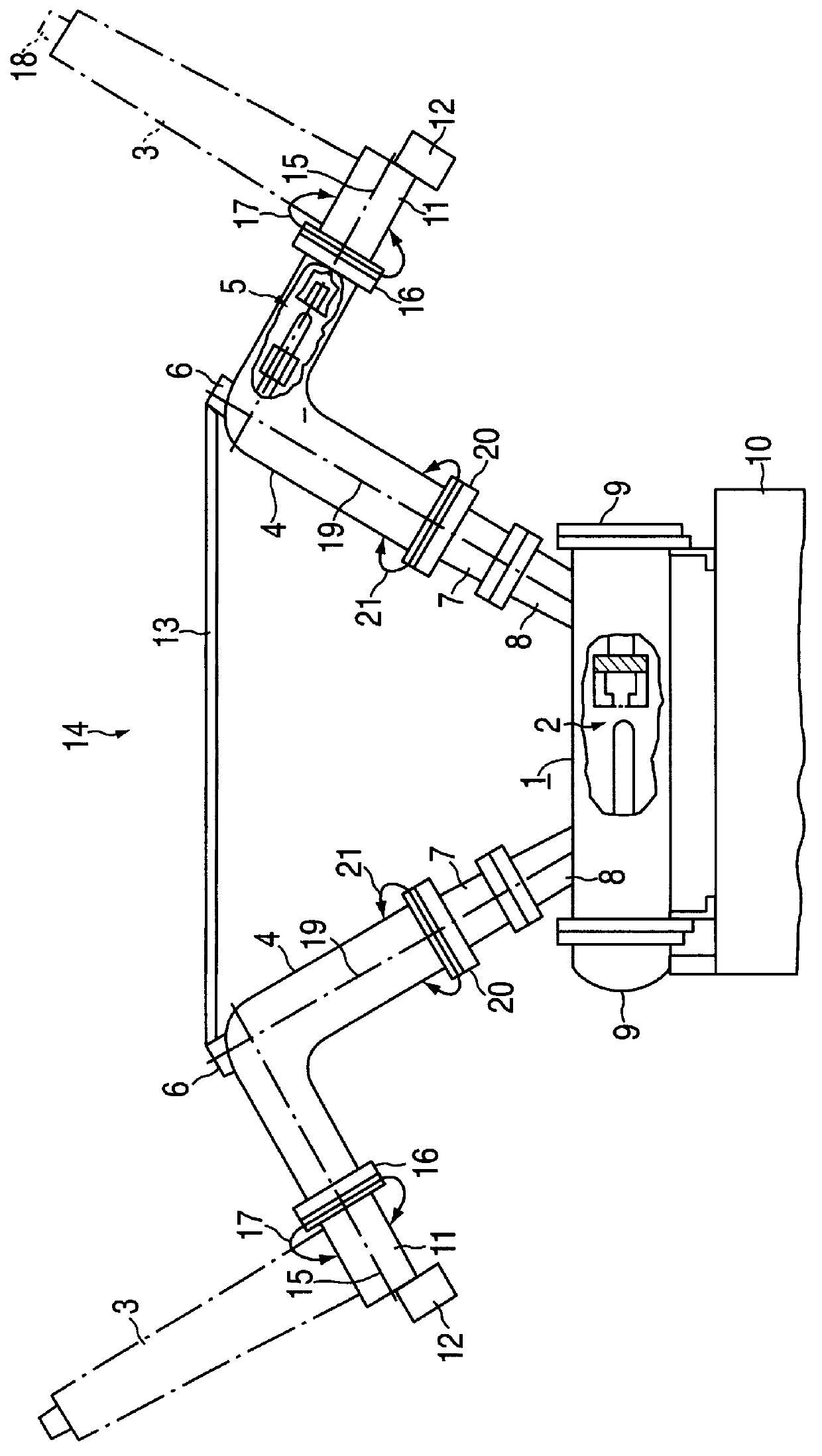
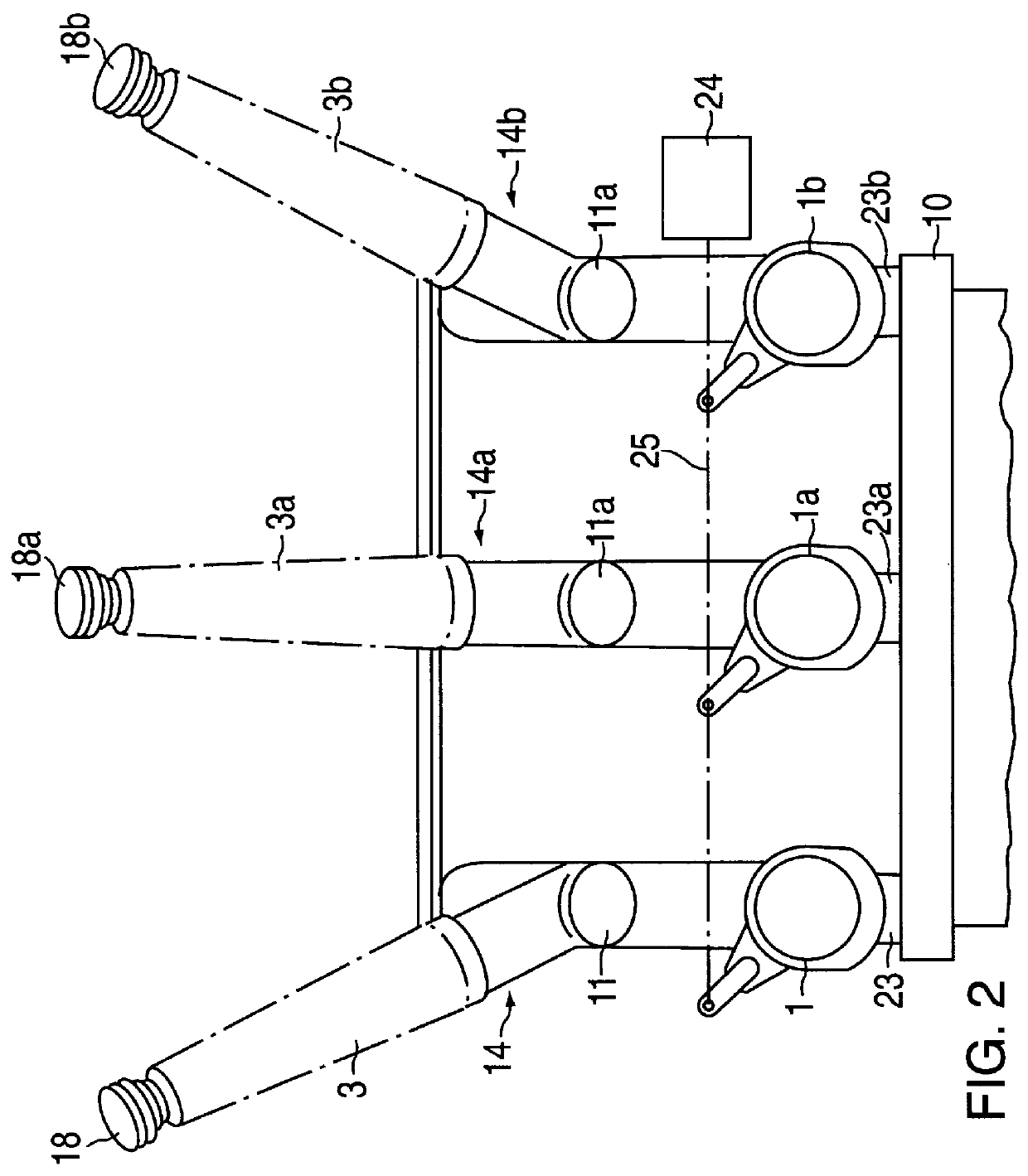
As FIG. 1 shows, central enclosure housing 1, which houses circuit breaker 2, accommodates two lead-in insulators 3, which are symmetrically inclined away from one another in order to guarantee sufficient space to other terminals for the respective overhead line terminal. Lead-in insulators 3 are accommodated with an additional housing 4, in which there is an insulating switch 5 and a ground electrode 6, connected between them. In the example embodiment shown in FIG. 1, additional housing 4 is, for example, an elbow-shaped housing. Additional housing 4 is connected, via a part 7 of additional housing 4, accommodating a current transformer (not shown), and via a connection piece 8, to central enclosure housing 1 forming an acute angle with sides 9 of central enclosure housing 1 mounted on rack 10 of the high-voltage switchgear. Lead-in insulators 3 are fastened to a part 11 of additional housing 4, on which high-speed grounding switch 12 is located. Brace element 13 is used to stabil...


PUM


Abstract

PCT No. PCT / DE97 / 01694 Sec. 371 Date May 28, 1999 Sec. 102(e) Date May 28, 1999 PCT Filed Aug. 6, 1997An attachment of high-voltage lead-in insulators (1, 1') on enclosure housings (1, 1') using elbow-shaped additional housings which have rotary joints to allow the insulators to rotate in order to maintain a connection distance.

Description

The present invention relates to a three-pole, gas-insulated high-voltage switchgear having three metallic enclosure housings arranged next to one another, one for each circuit breaker, in which two lead-in insulators are arranged on each enclosure housing, and the lead-in insulators of both outer enclosure housings are laterally inclined away from the central enclosure housing.BACKGROUND INFORMATIONEuropean Patent No. 0 560 588 describes that a required insulating distance is provided between terminals of both lead-in insulators of an enclosure housing of each pole of a high-voltage switchgear accommodating a circuit breaker by arranging the lead-in insulators so that they are inclined away from one another forming a symmetrical V shape. In order to maintain the required insulating distance between the terminals of the lead-in insulators of adjacent enclosure housings of a three-pole, gas-insulated, metal-enclosed high-voltage switchgear that accommodate the circuit breaker, accord...

Claims


Application Information

Patent Timeline
Patent Type & Authority Patents(United States)
IPC IPC(8): H02B5/00H02B5/06H02B13/035
CPCH02B13/0352H02B5/06
Inventor MEINHERZ, MANFRED
Owner SIEMENS AG
Why Eureka
Try Eureka