Hydraulically-operated micromanipulator apparatus

a micromanipulator and hydraulic technology, applied in the direction of fluid couplings, mechanical control devices, instruments, etc., can solve the problems of inability to accurately observe or operate, the tip end of the microtool drifting, and the volume of hydraulic fluid may also chang

Inactive Publication Date: 2000-10-17
NARISHIGE
View PDF6 Cites 39 Cited by
  • Summary
  • Abstract
  • Description
  • Claims
  • Application Information

AI Technical Summary

Problems solved by technology

However, in micromanipulators operable by hydraulic pressure, such as oil pressure or water pressure, when ambient temperature changes, the volume of hydraulic fluid may also change.
This leads to drift of the tip end of the microtool, and hence accurate observation or operation is not achieved.
However, in such micromanipulator, the tip end of the microtool drifts when it is subject to electric hindrance.
The problems relating to drift, therefore, remain unsolved.
Such problems are serious when a long period of observation or operation is carried out while the tip end of the microtool is abutting to a sample.

Method used


Image

  • Hydraulically-operated micromanipulator apparatus
  • Hydraulically-operated micromanipulator apparatus
  • Hydraulically-operated micromanipulator apparatus

Examples


first embodiment

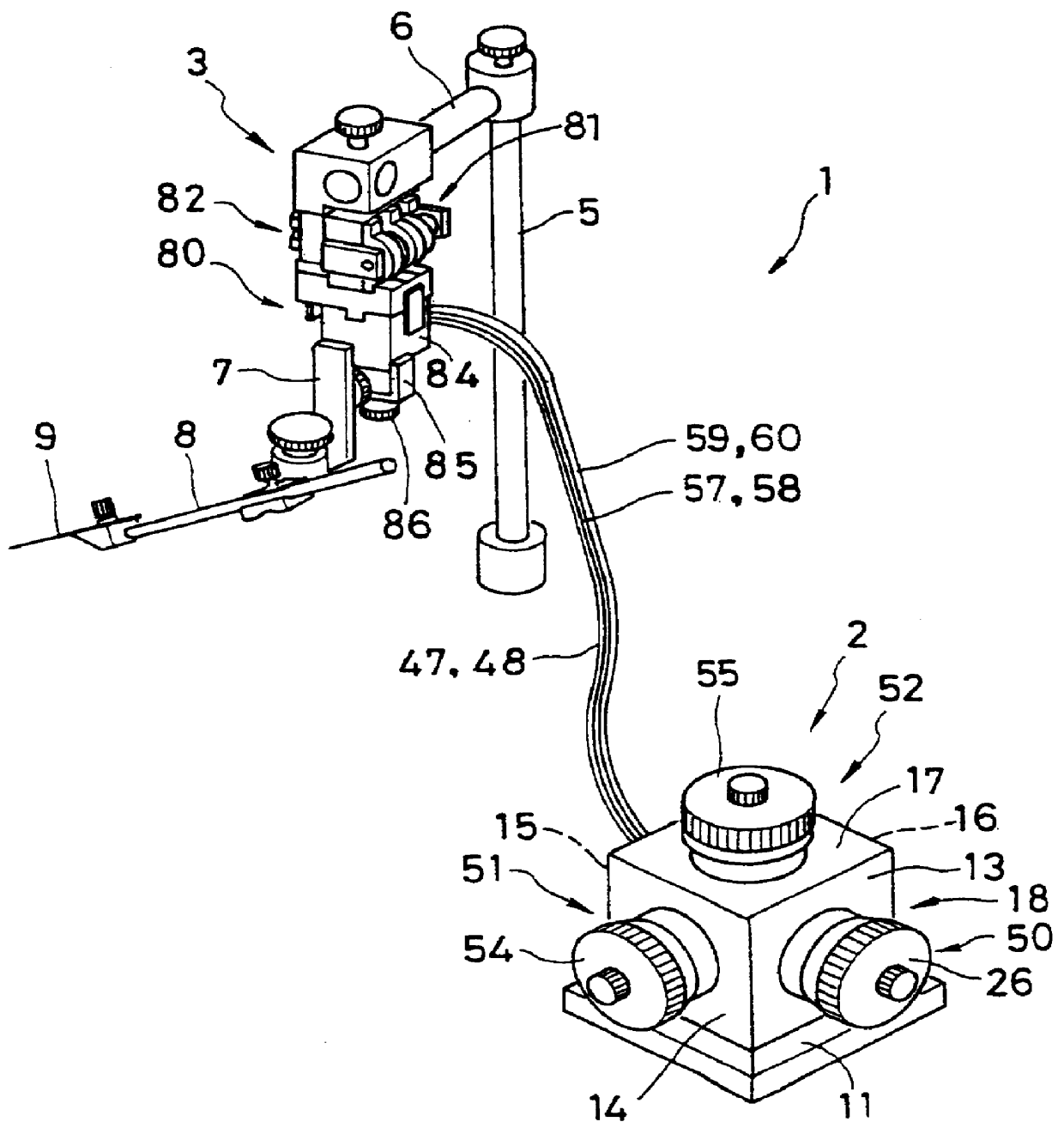
Referring now to FIG. 2, a hydraulically-operated micromanipulator apparatus according to the present invention is shown, in which the micromanipulator apparatus 1 comprises a micromanipulator fine control unit 2 having handles for three-directional control and a hydraulically-operated micromanipulator 3. The micromanipulator fine control unit 2 is connected to the hydraulically-operated micromanipulator 3 (hereinafter referred to as a micromanipulator) through a plurality of hoses 47, 48, 57, 58, 59, 60. The micromanipulator 3 is fixed to a mounting bar 6 which is supported to a pole 5. A tightening device 7 is mounted on the micromanipulator 3 for supporting a holder 8. A microtool 9 is attached to the front end of the holder 8.

A micromanipulator fine control unit 2 has a base plate 11 to which is mounted four side plates 13, 14, 15, 16 and a top plate 17. The base plate 11, the four side plates 13, 14, 15, 16 and the top plate 17 are fixed to each other, thereby providing a case ...

second embodiment

a hydraulically-operated micromanipulator apparatus according to the present invention will be described with reference to FIGS. 12 to 16. Referring particular to FIG. 12, the hydraulically-operated micromanipulator apparatus 101 comprises an operating unit 102 and an actuating unit 103.

The operating unit 102 includes a Z-axis dial 121, an X-axis dial 122 and a Y-axis dial 123 as fine control means for the respective Z, X, Y axes control. As shown in FIG. 13 (a), the Z-axis dial 121 comprises a control handle 121A and a bearing 121B. The control handle 121A is provided with a male thread portion 121a. A tubular push portion 121C is further provided at the front end of the male thread portion 121a.

The bearing 121B is provided with an internal thread portion 121b for the engagement with the male thread portion 121a of the control handle 121A. Provided outer periphery of the bearing 121B is a scale mark 121c for the reference of a fine control operation. A hydraulic oil chamber 141 as ...

third embodiment

a hydraulically-operated micromanipulator apparatus according to the present invention will be described below with reference to FIGS. 17 to 22. Referring particular to FIG. 17, the hydraulically-operated micromanipulator apparatus 201 comprises an operating unit 202 and an actuating unit 203.

The operating unit 202 includes a Z-axis fine control dial 221, an X-axis fine control dial 222 and a Y-axis fine control dial 223 as fine control means for the respective Z, X, Y axes control, and also a Z-axis coarse control dial 224, an X-axis coarse control dial 225 and a Y-axis coarse control dial 226 as coarse control means for the respective Z, X, Y axes control. As shown in FIG. 18 (a), the Z-axis fine control dial 221 comprises a control handle 221A and a bearing 221B. The control handle 221A is provided with a male thread portion 221a. A tubular push portion 221C is further provided at the front end of the male thread portion 221a.

The bearing 221B is provided with an internal thread p...


PUM

PropertyMeasurementUnit
temperatureaaaaaaaaaa
displacementaaaaaaaaaa

Abstract

A hydraulically-operated micromanipulator apparatus is disclosed. The micromanipulator apparatus comprises: a micromanipulator fine control unit including an operating-side piston finely movable with respect to an operating-side hydraulic cylinder and fine control means, either the operating-side piston or the operating-side hydraulic cylinder being stationarily retained, while the rest being finely operable by the fine control means; a hydraulically-operated micromanipulator including an actuating-side piston finely movable with respect to an actuating-side hydraulic cylinder and a fine displacement member, the actuating-side hydraulic cylinder being connected to said operating-side hydraulic cylinder through a hose, either the actuating-side piston or the actuating-side hydraulic cylinder being stationarily retained, while the rest being attached to the fine displacement member; and compensating means for compensating a pressure change of the hydraulic fluid between said operating-side hydraulic cylinder and said actuating-side hydraulic cylinder when ambient temperature changes.

Description

1. Field of the InventionThe present invention relates to hydraulically-operated micromanipulator apparatus including microtools, such as a glass electrode positioned in the field of a microscope with the use of hydraulically-operated remote controlling means.2. Prior ArtIn basic medical science or biotechnology, micromanipulators are used for treating cells, such as creature's organs, cellular textures, egg cells and the like. These cells are treated in various operations for example suctioning, injecting and dividing by finely controlling a microtool in the field of a microscope.However, when an operator finely controls the micromanipulator by his direct contact with its control handle, his hand trembling may be multiplied and transmitted to the microtool through the body frame. For this reason, care should be taken for finely controlling the micromanipulator. Since the micromanipulator needs to be gently operated without hand trembling, delicate operations, the greatest possible ...

Claims


Application Information

Patent Timeline
Patent Type & Authority Patents(United States)
IPC IPC(8): C12M3/00G02B21/32B25J7/00
CPCB25J7/00G02B21/32C12M35/00Y10T74/20378
Inventor YONEYAMA, SHINJI
Owner NARISHIGE
Why Eureka
Try Eureka