Electrical connector assembly having protection partition

Inactive Publication Date: 2000-10-17
HON HAI PRECISION IND CO LTD
View PDF3 Cites 27 Cited by
  • Summary
  • Abstract
  • Description
  • Claims
  • Application Information

AI Technical Summary

Problems solved by technology

As ultra SCSI connectors have been made in the form of IDC connector, mating/withdrawing between two ultra SCSI connectors become a problem because the normal force existed between two mated connect

Method used


Image

  • Electrical connector assembly having protection partition
  • Electrical connector assembly having protection partition
  • Electrical connector assembly having protection partition

Examples


Embodiment Construction

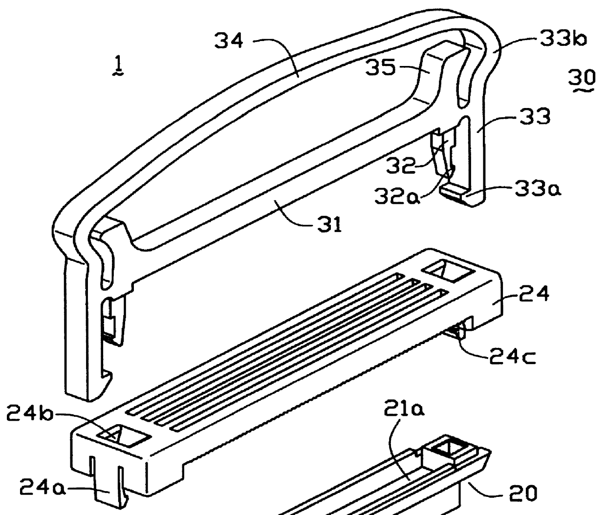
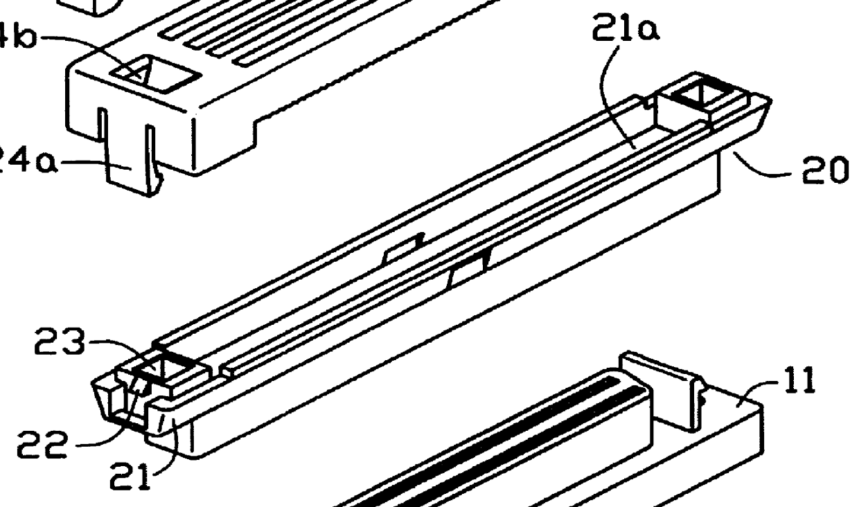
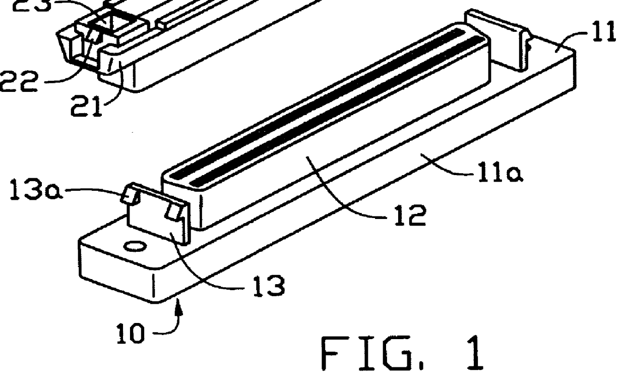
Referring to FIGS. 1, 2, and 3, an electrical connector assembly 1 in accordance with the present invention comprises a first connector 10 and a second connector 20 mated to the first connector 10. In the preferred embodiment, the first connector 10 is a female ultra SCSI connector and the second connector 20 is an IDC SCSI connector. The first connector 10 can be assembled to a printed circuit board (not shown).

The first connector 10 includes a first housing 11 having a base plate 11a forming an island portion 12 thereof. A pair of hooks 13 is formed on the base plate 1a. Each hook 13 includes a projection 13a extending outward. The second connector 20 includes a second housing 21 defining a cavity (not labeled) for receiving the island portion 12 of the first connector 10. The second housing 21 has a termination face 21a opposite to the cavity. A pair of mounting wedges 22 is formed on opposite ends thereof. The second housing 21 further defines a pair of retaining recesses 23 adj...


PUM


Abstract

An electrical connector assembly, comprises a first connector assembled to a printed circuit board and a second connector releasably mated thereto. The second connector mated to the first connector includes a second housing defining a cavity for receiving an island portion of the first connector. The second housing forms a pair of mounting wedges at ends thereof and retaining recesses adjacent to the mounting wedges. A termination cover assembled to the second connector includes a pair of mounting lugs engaged to the mounting wedges. A pair of passages defined in the cover adjacent to the mounting lugs. A strain relief assembled to the termination cover forms inner latches engaged to the retaining recess and outer latches pivotally hinged to the base bar. The outer latches are releasably received in the retaining recess of the first connector when the second connector is mated to the first connector.

Description

The present invention relates to an electrical connector assembly, and more particularly to an assembly having a first connector and a second connector mated to the first connector. Interconnection between the first and second connectors is affirmed by a strain relief having inner latches which are well protected from being accidentally released during mating of the first and second connectors.DESCRIPTION OF PRIOR ARTConventionally, an IDC connector assembled to an end of a cable is directly plugged to a complimentary connector (normally a header connector) mounted on a printed circuit board. The termination between insulation displacement portions and conductors of the cable is facilitated by a termination cover assembled to the housing of the IDC connector. In order to prevent the termination from being accidentally separated during withdraw of the IDC connector from the header, one of the approach is to provide a strain relief assembled to the termination cover thereby preventing...

Claims


Application Information

Patent Timeline
IPC IPC(8): H01R13/506H01R13/502H01R13/58
CPCH01R12/675H01R13/5812H01R13/506
Inventor HWANG, JENG-YIH
Owner HON HAI PRECISION IND CO LTD
Why Eureka
Try Eureka