Variable speed control for AC induction motors

a technology of variable speed control and induction motor, which is applied in the direction of electric controller, motor/generator/converter stopper, dynamo-electric converter control, etc., can solve the problems of inefficient behavior of most motors, waste of power and hea

Inactive Publication Date: 2000-10-31
CUMMINS MICHAEL D
View PDF3 Cites 13 Cited by
  • Summary
  • Abstract
  • Description
  • Claims
  • Application Information

AI Technical Summary

Benefits of technology

It is one of the main objects of the present invention to provide a variable speed control for AC motors that k

Problems solved by technology

If this ratio is not maintained, then the torque at 30 Hz. will be 200% the torque at 60 Hz. with the consequent waste of power and

Method used


Image

  • Variable speed control for AC induction motors
  • Variable speed control for AC induction motors
  • Variable speed control for AC induction motors

Examples


Embodiment Construction

Referring now to the drawings, where the present invention is generally referred to with numeral 10, it can be observed that it basically includes universal conmutator or microcontroller 20 that activates H-bridge driver circuit 40 that in turn activates t e electronic switches in H-bridge 60. A suitable D.C. power supply 80 feeds these circuits and coil C of induction motor M.

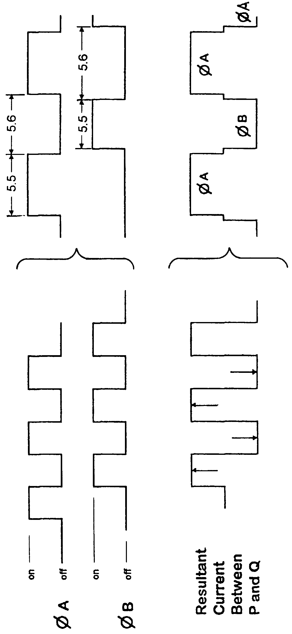
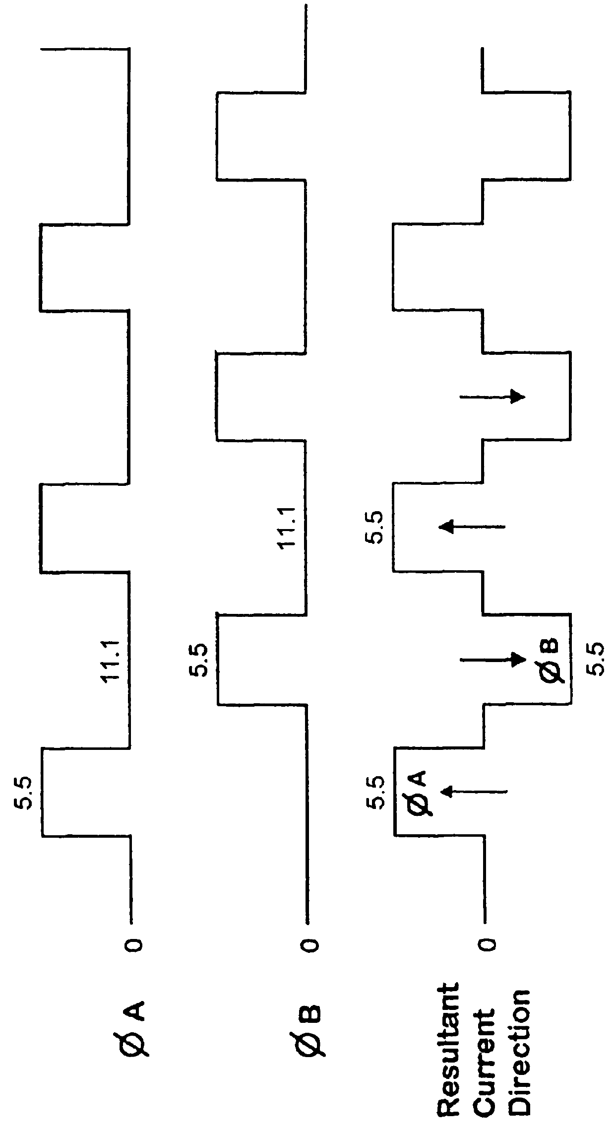
Universal conmutator or microcontroller 20 is implemented with a device as described in my patent entitled Universal Commutator for A.C. motors issued on Nov. 17, 1998 under U.S. Pat. No. 5,838,134, incorporated by reference here, and permits a user to avoid he contention in the switching operation through the implementation of "dead times". But, additionally, a user controls the duty cycle of the driving signals for phases "A" and "B" to keep the necessary ratio between the voltage applied and the frequency (or the angular speed of the motor). At start up, for instance, the motor tries to overcome the inertia...


PUM


Abstract

A speed control apparatus for varying the speed of an AC motor while maintaining the torque and power constant over a range of angular speeds The AC motor is driven by a D.C. source. A universal conmutator capable of providing two symmetrical non-contending signals with a frequency that can be selectively varied. A microprocessor unit for monitoring the frequency of the signals and control proportionally varying the duty cycle of the signals calculates the necessary duty cycle to maintain the torque constant over a range of angular speeds.

Description

II. BACKGROUND OF THE INVENTION1. Field of the InventionThe present invention relates to variable speed controls for AC motors, and more particularly, to those that are driven by DC sources.2. Description of the Related ArtIn line operated AC induction motors, speed / torque / efficiency is related to line voltage and frequency (voltage / frequency). For example, a 2-pole AC motor designed to operate at a line voltage / frequency of 120 volts AC and 60 Hz rotates at 3600 R.P.M. and depending on the winding characteristics will provide a given torque. If this same motor is operated at 30 Hz. (1 / 2 the frequency), the motor should rotate at 1800 R.P.M. (half the speed) but at greater torque with the consequent increase in power dissipation in the form of heat generated. Thus, to maintain the same torque (and similar power dissipation) at this lower frequency, the voltage needs to be reduced to one half of the original 120 volts AC, or 60 volts AC. The V / f ratio is then maintained substantially...

Claims


Application Information

Patent Timeline
IPC IPC(8): H02P25/02H02P25/04
CPCH02P25/04
Inventor CUMMINS, MICHAEL D.
Owner CUMMINS MICHAEL D
Why Eureka
Try Eureka