Device for measuring the mass of a flowing medium of air aspirated by an internal combustion engine

a technology of internal combustion engine and flow rate meter, which is applied in the direction of volume metering, machines/engines, instruments, etc., can solve the disadvantages of characteristic curve measurement elements, sagging of wire grids, and inability to combine relatively complicated and expensive flow rectifiers with grids of different mesh widths

Inactive Publication Date: 2000-11-07
ROHM & HAAS CO +1
View PDF5 Cites 23 Cited by
  • Summary
  • Abstract
  • Description
  • Claims
  • Application Information

AI Technical Summary

Problems solved by technology

Embedding the wire grid in the plastic has the disadvantage that if there is a temperature change, and when the plastic of the flow rectifier ages, creepage can cause sagging of the wire grid.
However, the sagging of the wire grid causes shifting among the individual wires of the grid, and as a consequence the characteristic curve the measurement element is disadvantageously altered.
Because the grid is permanently secured to the flow rectifier, there is also the disadvantage that only relatively complicated and expensive flow rectifiers w

Method used


Image

  • Device for measuring the mass of a flowing medium of air aspirated by an internal combustion engine
  • Device for measuring the mass of a flowing medium of air aspirated by an internal combustion engine
  • Device for measuring the mass of a flowing medium of air aspirated by an internal combustion engine

Examples


Embodiment Construction

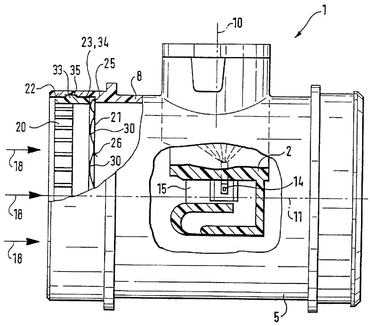
In FIG. 1, a device 1 for measuring the mass of a flowing medium, or flow rate meter, especially for measuring the flow rate of the air aspirated by internal combustion engines, is shown. The engine may be a mixture-compressing engine with externally supplied ignition, or an air-compressing engine with self-ignition. The device 1 has a measurement part 2, which is introduced, for instance in plug-in fashion, into a measurement stub 5 of the device 1. The measurement part 2 is by way of example slender, rodlike, and parallelepiped in shape, extending in elongated fashion in the direction of a plug-in shaft 10, and is introduced, for instance in plug-in fashion, into an opening made in a wall 8 of the measurement stub 5. The wall 8 defines a flow cross section, for example of circular cross section, in the middle of which a center axis 11 extends, this axis being oriented in the direction 18 of the flowing medium, parallel to the wall 8, and perpendicular to the plug-in shaft 10. The ...


PUM


Abstract

PCT No. PCT/DE97/01934 Sec. 371 Date Jul. 14, 1998 Sec. 102(e) Date Jul. 14, 1998 PCT Filed Aug. 29, 1997 PCT Pub. No. WO98/21554 PCT Pub. Date May 22, 1998Known devices for measuring the mass of a flowing medium, or flow rate meters, have a measurement element accommodated in a measurement stub, and a flow rectifier with a grid is provided upstream of the measurement element. For easy production and assembly and accurate alignment of a grid (21) with a flow rectifier (20) of the device (1), the grid (21) has integrally formed-on spring elements (30), which deform elastically when the flow rectifier (20) is installed so that by their spring force, in combination with a detent connection (33, 35) provided on the flow rectifier (20), they durably retain the flow rectifier (20) and the grid (21). The device is intended for measuring the mass of a flowing medium, especially for measuring the flow rate of air aspirated by internal combustion engines.

Description

PRIOR ARTThe invention is based on a device for measuring the mass of a flowing medium, or flow rate meter, for air aspirated by an internal combustion engine. A device is already known (European Patent 0 458 998) that has a measurement element accommodated in a measurement stub, with a flow rectifier and a grid accommodated upstream of the measurement element. The flow rectifier is intended to generate as uniform a flow as possible over the entire inside cross section. The grid, durably secured in the flow rectifier, is intended to create superfine eddies in the flow, so that the flow conditions downstream of the grid can be made as constant as possible for the sake of stabilizing the measurement signal. To avoid a deviation from the characteristic curve of the measurement signal output by the measurement element, it is especially important that the grid be disposed in a precise alignment with the flow rectifier. This is done, in the known device, by embedding the grid in the heate...

Claims


Application Information

Patent Timeline
IPC IPC(8): F02M69/48F02M69/46G01F1/684G01F15/00G01F1/00G01F1/68G01F15/12
CPCF02M69/48G01F15/00G01F1/6842
Inventor RILLING, HEINZ
Owner ROHM & HAAS CO
Why Eureka
Try Eureka