Temperature sensing and limiting device

Inactive Publication Date: 2000-11-21
CERAMASPEED ACQUISITION COMPANY
View PDF12 Cites 10 Cited by
  • Summary
  • Abstract
  • Description
  • Claims
  • Application Information

AI Technical Summary

Benefits of technology

The arrangement of the invention provides a temperature sensing component and bimetallic safety cut-out device as a compact, integrated u

Problems solved by technology

Such devices are restricted in operation to one predetermined temperature and exhibit a significant tolerance (typically .+-.5%) deviating about this predetermined temperature, as a result of variations of manufactured components and limitations of assembly processes.
The ability to operate at a higher temperature for the glass-ceramic cooking surface leads to improved boiling performance especially with high power heaters and poor quality cooking utensils.
A proble

Method used


Image

  • Temperature sensing and limiting device
  • Temperature sensing and limiting device
  • Temperature sensing and limiting device

Examples


Embodiment Construction

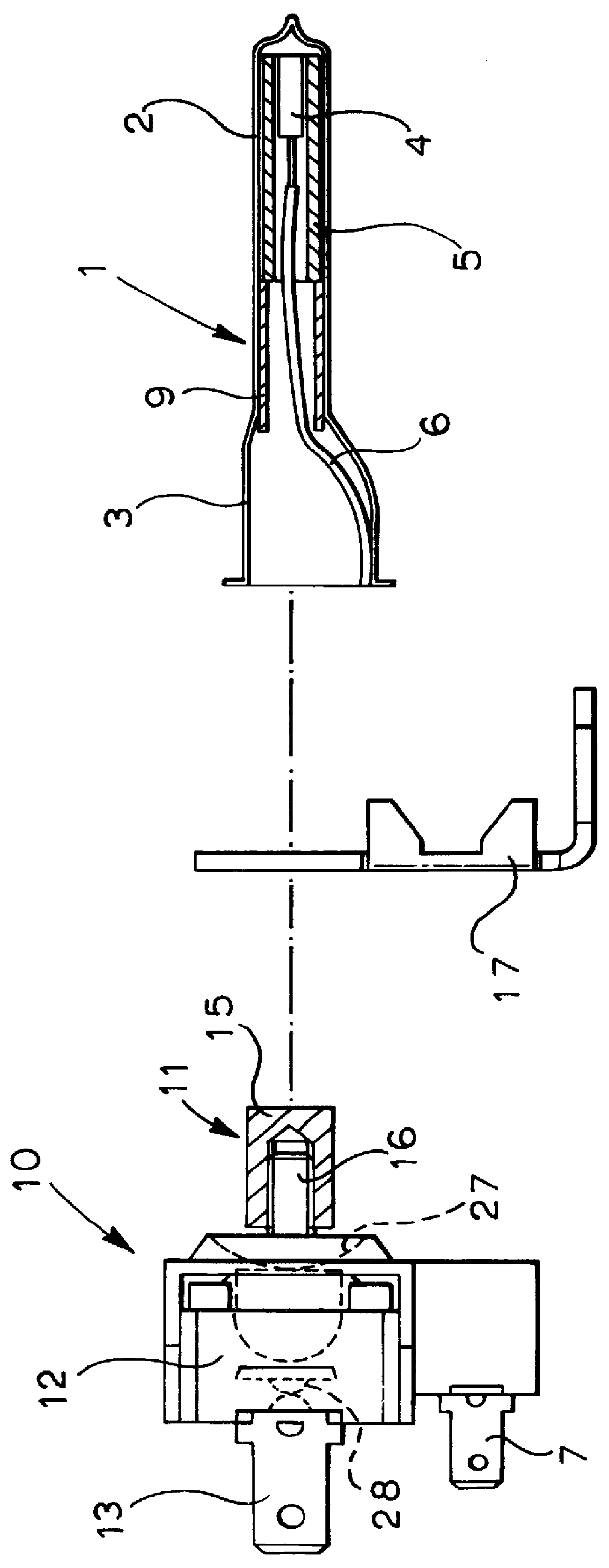
A temperature sensing and limiting device for a radiant electric heater, particularly for a glass-ceramic cooking appliance, has a housing comprising an elongate tubular member 1. The tubular member 1, comprises a metal such as stainless steel, but could comprise another suitably high temperature withstanding material, such as a ceramic. The tubular member 1 has a relatively narrow portion 2, which may be closed at its end if required, and a wider opposite end portion 3.

Inserted in the tubular member 1 at the narrow end portion 2 is a temperature-sensing component 4 providing an electrical parameter which changes as a function of temperature. This component may comprise a platinum resistance temperature detector, whose electrical resistance changes as a function of temperature. However it could comprise another resistance device having either PTC or NTC characteristics or could comprise a capacitor or an inductor, or a thermo-electric device such as a thermocouple. In addition to el...


PUM


Abstract

A temperature sensing and limiting device is described for use in a radiant electric heater (8) incorporating at least one heating element (14). The device comprises an elongate tubular housing (1) adapted to at least partly traverse the heater so as to be heated externally by the heating element. A component (4) is provided within the housing and provides an electrical parameter which changes as a function of temperature. At least a thermal-sensing portion (11) of a thermally-responsive bimetallic cut-out device (10) is provided within the housing (1), the cut-out device being adapted to deenergize the heater (8) at a predetermined temperature.

Description

This invention relates to the sensing and limiting of temperature in a radiant electric heater, such as for example in a cooking appliance, particularly a glass-ceramic cooking appliance.DESCRIPTION OF PRIOR ARTIt has been well-known for many years to provide heaters in glass-ceramic cooking appliances with temperature limiting devices arranged to sense the temperature particularly of the glass-ceramic cooking surface and to deenergise the heaters at a predetermined temperature to prevent overheating of the glass-ceramic. Such temperature limiting devices commonly comprise a differentially-expanding rod-in-tube assembly having one end thereof arranged to activate mechanical switch means. Such devices are restricted in operation to one predetermined temperature and exhibit a significant tolerance (typically .+-.5%) deviating about this predetermined temperature, as a result of variations of manufactured components and limitations of assembly processes.There are increasing requirement...

Claims


Application Information

Patent Timeline
IPC IPC(8): H05B3/68H05B1/02H05B3/74
CPCH05B1/0213H05B3/746H05B2213/04
Inventor WILKINS, PETER RAVENSCROFT
Owner CERAMASPEED ACQUISITION COMPANY
Why Eureka
Try Eureka