Disk device having a flexible printed circuit cable providing a small-height structure

a flexible printed circuit cable and disk device technology, applied in the direction of data recording, instruments, record carrier construction details, etc., can solve the problems of high manufacturing cost of the conventional cd-rom disk device 100, difficult to design a cd-rom disk device having a small size and a small height, etc., to achieve the effect of reducing manufacturing cos

Inactive Publication Date: 2000-11-21
TEAC CORP
View PDF7 Cites 66 Cited by
  • Summary
  • Abstract
  • Description
  • Claims
  • Application Information

AI Technical Summary

Benefits of technology

Another object of the present invention is to provide a disk device which includes a flexible printed circuit cable having a simple structure that provides a small height for the disk device.
Still another object of the present invention is to provide a disk device which includes a flexible printed circuit cable which is less expensive and provides a reduction of the manufacturing cost.
It is possible that the disk device of the present invention provides a small height for the disk device since the flexible printed circuit cable has a flat, single-layer structure to electrically connects the electrical parts of the moving unit to the printed circuit board of the chassis. Further, it is possible that the disk device of the present invention provides a reduced manufacturing cost since the flexible printed circuit cable having a flat, single-layer structure is less expensive than the multiple-layer structure cable of the conventional disk device.

Problems solved by technology

Accordingly, there is a problem that the manufacturing cost of the conventional CD-ROM disk device 100 becomes high because the FPC cable 120 having the multiple-layer structure is expensive.
It is difficult to design a CD-ROM disk device having a small size and small height in the case of the conventional CD-ROM disk device 100.

Method used


Image

  • Disk device having a flexible printed circuit cable providing a small-height structure
  • Disk device having a flexible printed circuit cable providing a small-height structure
  • Disk device having a flexible printed circuit cable providing a small-height structure

Examples


Embodiment Construction

A description will now be given of the preferred embodiments of the present invention with reference to the accompanying drawings.

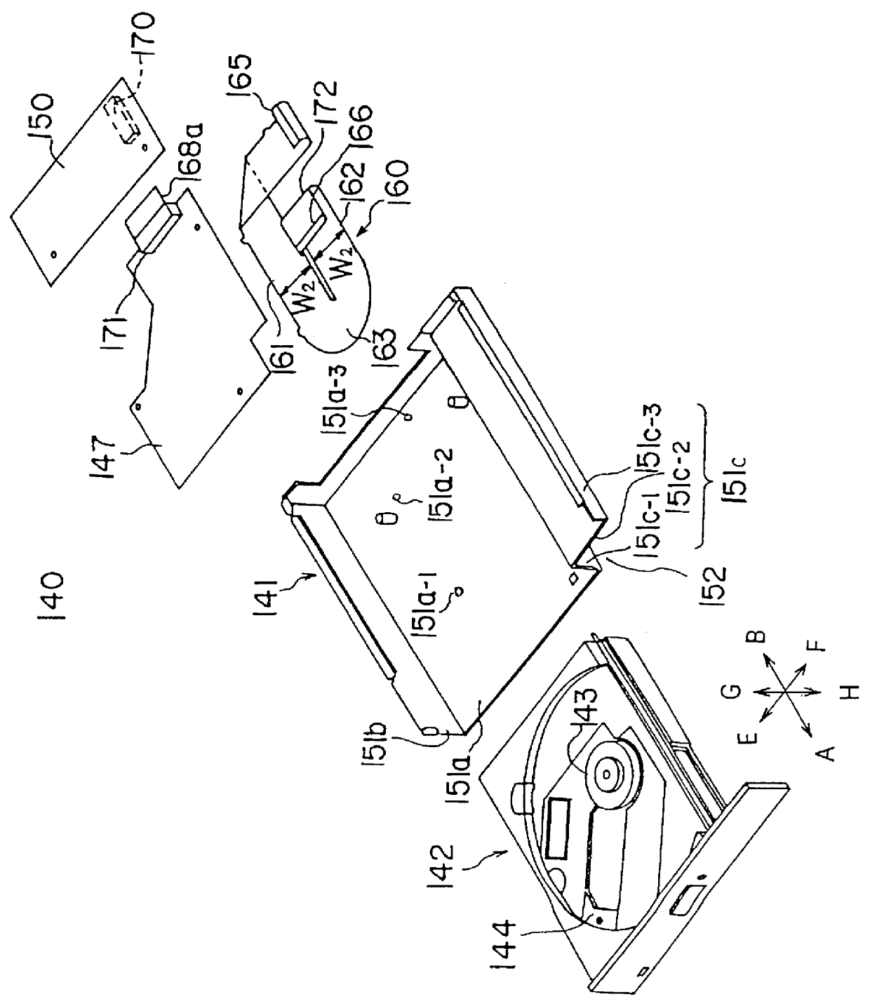
FIG. 3 shows a CD-ROM disk device 140 to which one embodiment of the present invention is applied. The disk device 140 generally has a chassis 141 and a moving unit 142.

FIG. 4 shows the CD-ROM disk device 140 when the moving unit 142 is placed at an inserted position. FIG. 5 shows the CD-ROM disk device 140 when the moving unit 142 is manually moved in an eject direction to a disk-change position. FIG. 6 is a top view of the CD-ROM disk device shown in FIG. 5. FIG. 7 is a cross-sectional view of the CD-ROM disk device 140 taken along a line VII--VII in FIG. 4.

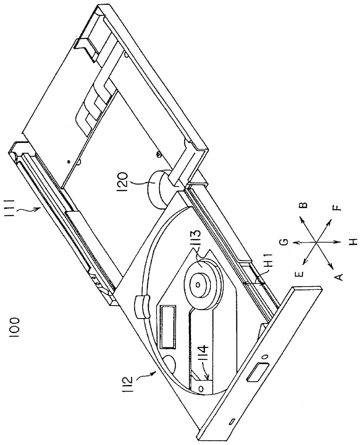
Referring to FIGS. 3 through 7, the moving unit 142 is a mechanical-parts carrying tray on which a CD-ROM (not shown) that is a computer-readable recording medium is held. Electrical parts are provided on the moving unit 142, and the electrical parts on the moving unit 142 include an optical pickup 1...


PUM

PropertyMeasurementUnit
anglesaaaaaaaaaa
widthaaaaaaaaaa
widthaaaaaaaaaa

Abstract

A disk device includes a chassis having a printed circuit board provided therein. A moving unit on which a recording disk is held has a sub-chassis and electrical parts on the sub-chassis, the moving unit being movably supported on the chassis so that the moving unit is movable between an inserted position and a disk-change position in an insert direction and an eject direction. A first connector is arranged on the sub-chassis of the moving unit, the first connector being electrically coupled to the electrical parts of the moving unit. A flexible printed circuit cable has a first connector portion fitted to the first connector so that the electrical parts of the moving unit are electrically connected to the printed circuit board of the chassis, the first connector portion being arranged under the sub-chassis of the moving unit.

Description

BACKGROUND OF THE INVENTION(1) Field of the InventionThe present invention generally relates to a disk device, and more particularly to a CD-ROM disk device, built in a casing of a small-size personal computer, wherein a moving unit on which a CD-ROM is held is movable between an inserted position and a disk-change position in both an insert direction and an eject direction.(2) Description of the Related ArtFIG. 1 shows a conventional CD-ROM disk device 100. The conventional CD-ROM disk device of this kind is disclosed in, for example, Japanese Patent Application No.6-45582 which is assigned to the assignee of the present invention. The CD-ROM disk device 100 shown in FIG. 1 is a built-in type that is installed in a casing of a notebook-size personal computer for use and operation. A CD-ROM (compact disk-read-only memory) is a type of optical disk which is capable of storing large amounts of information. The CD-ROM is accessed by an optical pickup of the CD-ROM disk device in order ...

Claims


Application Information

Patent Timeline
Patent Type & Authority Patents(United States)
IPC IPC(8): G11B33/12G11B17/04G11B19/20G11B21/02
CPCG11B17/056G11B33/122G11B33/121G11B21/02
Inventor WATANABE, TAKASHIFUJIMURA, NOBUHIKOKAMEI, YO
Owner TEAC CORP
Why Eureka
Try Eureka