Apparatus for generating electricity from flowing fluids

a technology of apparatus and fluid, applied in the direction of electric generator control, machine/engine, reaction engine, etc., can solve the problem of limiting the locations where these known devices may be deployed

Inactive Publication Date: 2000-11-28
CLARK ROBERT O
View PDF22 Cites 84 Cited by
  • Summary
  • Abstract
  • Description
  • Claims
  • Application Information

AI Technical Summary

Problems solved by technology

The use of fins and paddles to create rotary motion, for generators and the like, limits the locations where these known devices may be deployed, as rotary devices generally require comparatively high wind or water flow velocities.

Method used


Image

  • Apparatus for generating electricity from flowing fluids
  • Apparatus for generating electricity from flowing fluids
  • Apparatus for generating electricity from flowing fluids

Examples


Embodiment Construction

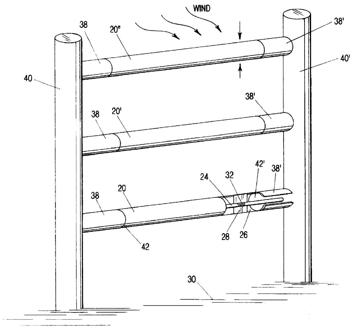
The invention has to do with the generation of electrical energy by tapping the forces of the wind or ocean tides. Thus, it is involved with the general fields of windmills and water mills. Importantly, the invention is an "aeolian" device. It is quite distinguishable from conventional wind or water mills, which typically involve placing some type of vane or paddle into the flowing fluid to cause rotary motion.

In the invention, the driving fluid does not induce any rotational movement in the inventive apparatus, but instead causes a principal component of the apparatus to oscillate. Also, the invention is not driven by wave action, and does not derive power from pulses or gusts; the device may be driven by a constant flow of water or wind.

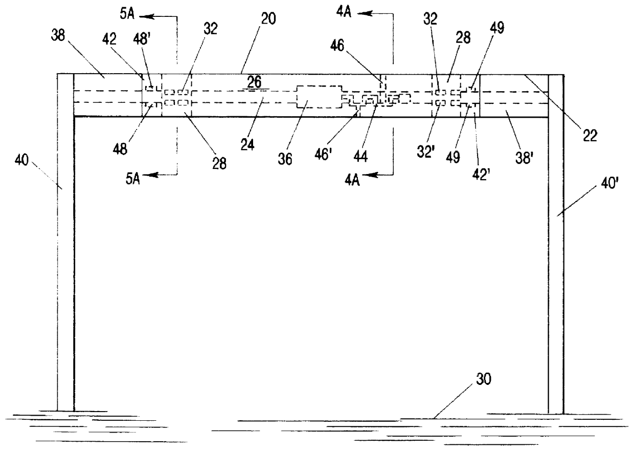
Briefly summarized, the inventive apparatus has one or more tubular vanes (which may be somewhat "wing-shaped"), that are mounted to be capable of to-and-fro motion in a single plane containing the axis of the vane. Stated differently, each vane do...


PUM


Abstract

An apparatus for generating electricity from aeolian oscilaltions caused by the flow of a fluid such as wind or water. An immobile beam extends between two piers, and a movable vane is disposed around the beam in parallel relation thereto. The vane is generally tubular, having a generally cylindrical or foil-shaped cross section. The movement of a fluid, such as wind or deep ocean tidal flow, past the vane induces aeolian oscillation in the vane, so that the vane moves to-and-fro, with respect to the beam, in a direction generally perpendicular to the direction of fluid flow. Rods and a crankshaft may connect the vane to a generator mounted upon the beam, so that the movement of the vane is converted into electricity. Alternatively, electricity can be generated from the movement of the vane by a field coil on the vane inducing electrical current in induction wires mounted upon the immobile beam.

Description

1. Field of the Invention (Technical Field)The present invention relates to apparatus for generating electricity from the movement of flowing fluids, and thus is related generally to windmill and water mill devices, and more particularly relates to an apparatus for generating electricity from aeolian oscillations due to ocean tides or wind.2. Background ArtWindmills and water mills have been used for centuries to harness the kinetic energy of wind and flowing water. Historically, most wind and water mills have involved devices incorporating fins or paddles. The fins or paddles are disposed mostly normal to the direction of wind or water stream flow, and upon some type of an axle, with the result that the force of the wind or water flow impinging against the fins or paddles induces a rotary motion of the axle. The rotating axle is then connected to some additional device for accomplishing work, such as a pump, electrical generator, millstone, or the like. More recently, the use of so...

Claims


Application Information

Patent Timeline
Patent Type & Authority Patents(United States)
IPC IPC(8): F03D5/00
CPCF03B17/06F03D5/00F03G7/08Y02E10/70Y02E10/28Y02E10/30Y02E10/20
Inventor CLARK, ROBERT O.
Owner CLARK ROBERT O
Why Eureka
Try Eureka