Detonator

a detonator and a technology for a detonator body, applied in the field of detonators, can solve the problems of complex selection, increased detonator and fabrication cost, and prone to wire breakage, and achieve the effect of less expensive manufacturing

Inactive Publication Date: 2000-12-12
EXCELITAS TECH SENSORS INC +1
View PDF61 Cites 50 Cited by
  • Summary
  • Abstract
  • Description
  • Claims
  • Application Information

AI Technical Summary

Benefits of technology

It is a further object of this invention to provide such a detonator which eliminates the need for the mechanical spacer elements and the resilient members asso...

Problems solved by technology

First, one important design consideration is that the explosive charge must contact the inside top surface of the transistor package can in order to prevent energy losses.
One problem with this prior art design is the complexity involved in choosing the structure and orientation of the resilient member which often includes incorporating two explosive charges separated by the resilient member.
And, these additional components add to the cost of the detonators and the man hours required for their fabrication.
Second, the lead posts of the transistor package base are typically connected to the lands of the chip slapper by individual wires.
These wires tend to break in the harsh environment described above and/or burn under the application of high amperage curren...

Method used


Image

  • Detonator
  • Detonator
  • Detonator

Examples


Embodiment Construction

Other objects, features and advantages will occur to those skilled in the art from the following description of a preferred embodiment and the accompanying drawings, in which:

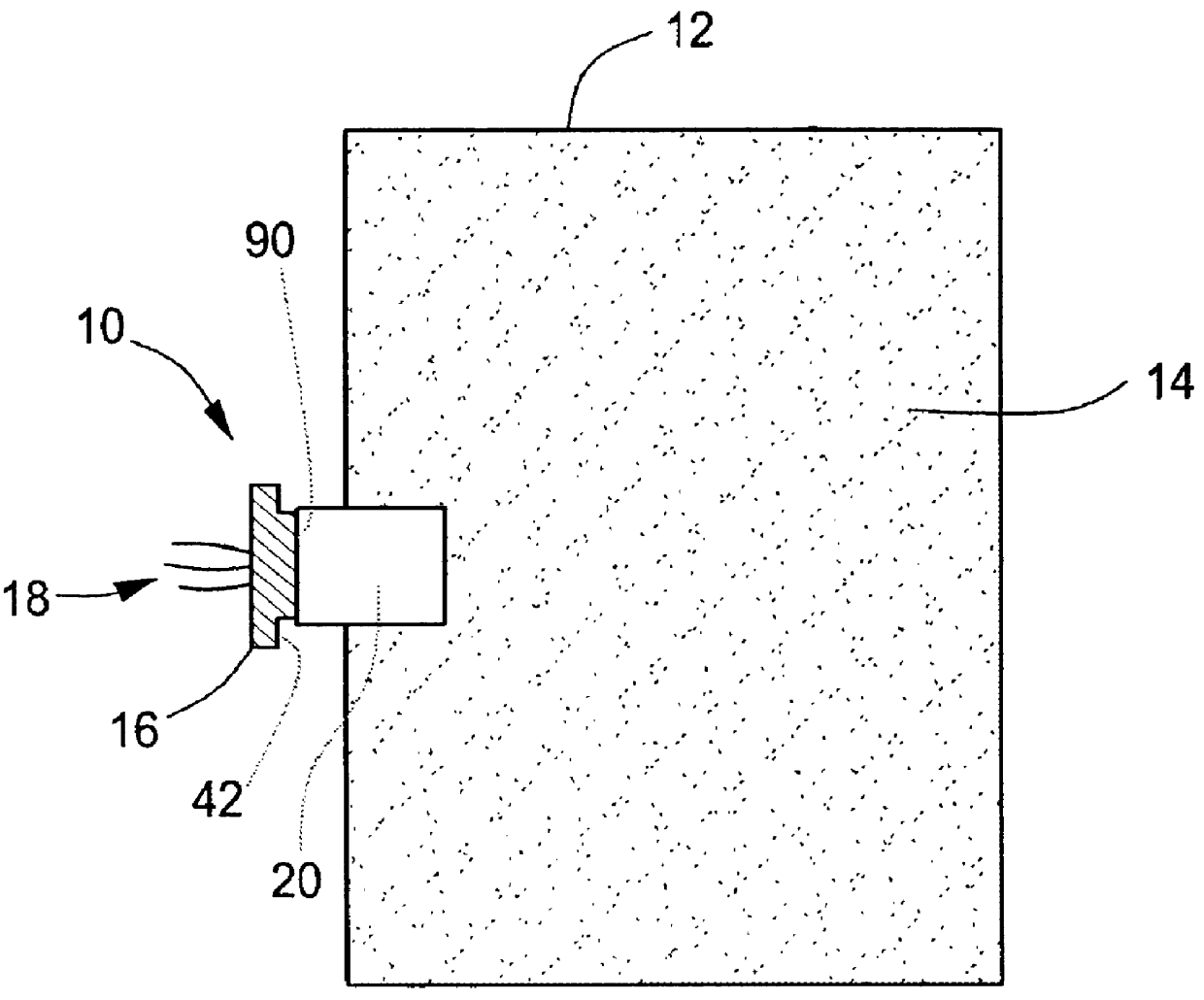
FIG. 1 is a schematic side sectional view of the detonator of this invention in place within a bulkhead containing a main charge to be detonated;

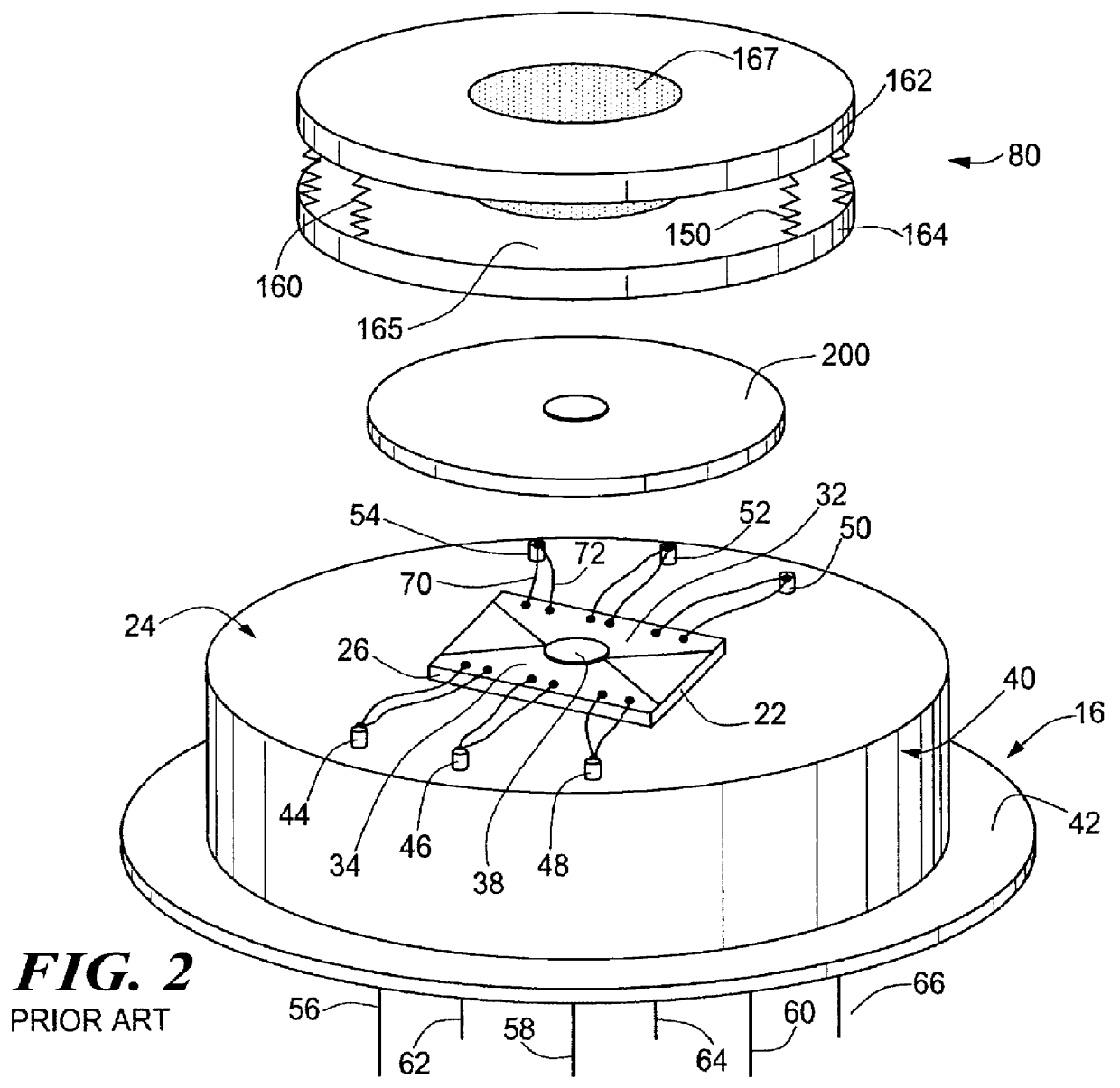
FIG. 2 is a schematic exploded view of a prior art detonator including two charges separated by resilient member and a number of individual lead post connecting wires;

FIG. 3 is a schematic side sectional view of a complete prior art detonator assembly;

FIG. 4 is a schematic side sectional view of the complete detonator assembly of the subject invention;

FIG. 5 is a schematic view of the base portion of the detonator in accordance with this invention;

FIG. 6 is a side sectional partially exploded view of a preferred embodiment of the connecting barrel of this invention; and

FIG. 7 is a schematic three dimensional view of the bottom portion of the connecting barrel shown in ...


PUM


Abstract

A detonator with a base portion including a header wall terminating in a support surface; an initiator on the support surface; an explosive charge spaced from the initiator; and a cap having an interior top surface and an enclosure wall extending downward from the interior top surface and surrounding the initiator and the explosive charge. The wall terminates in a rim secured at a location along the header wall corresponding to the thickness of the initiator, the spacing between the initiator and the explosive charge, and the thickness of the explosive charge thereby ensuring that the explosive charge is in communication with the interior top surface of the cap.

Description

This invention relates to detonators and in particular to chip slapper type detonators and a method of making the same.BACKGROUND OF INVENTIONDetonators are used to detonate a main charge such as an explosive of an air to surface missile. Such detonators are also used to detonate explosives used in other tactical devices, construction explosives, rocket boosters, and the like. These types of detonators must be physically robust and of high integrity. For example, an air to surface missile may be designed to pierce a bunker or other building and only then detonate the primary explosive. The detonator must, therefore, survive the shock of the launch and the impact with the bunker.Exploding foil initiator ("EFI") detonators, (e.g. "chip slappers"), generally include a ceramic chip upon which is deposited two opposing conductive copper lands which taper to a narrow "bridge" portion therebetween. An electrical current is provided to the lands at the time of initiation and the bridge port...

Claims


Application Information

Patent Timeline
IPC IPC(8): F42B3/12F42B3/00
CPCF42B3/124
Inventor NEYER, BARRY T.ADAMS, JOHN T.TOMASOSKI, ROBERT J.
Owner EXCELITAS TECH SENSORS INC
Why Eureka
Try Eureka