

Shifting device for synchromesh-type transmission
a technology of shifting device and transmission shaft, which is applied in the direction of gearing control, gearing element, belt/chain/gearing, etc., can solve the problems of sudden trouble in the driving system and insufficient detection of the input rotation chang
- Summary
- Abstract
- Description
- Claims
- Application Information
AI Technical Summary
Benefits of technology
Problems solved by technology
Method used
Image

Examples
Embodiment Construction
1. Field of the Invention
This invention relates to a shifting device for synchomesh-type transmission.
2. Related Background Art
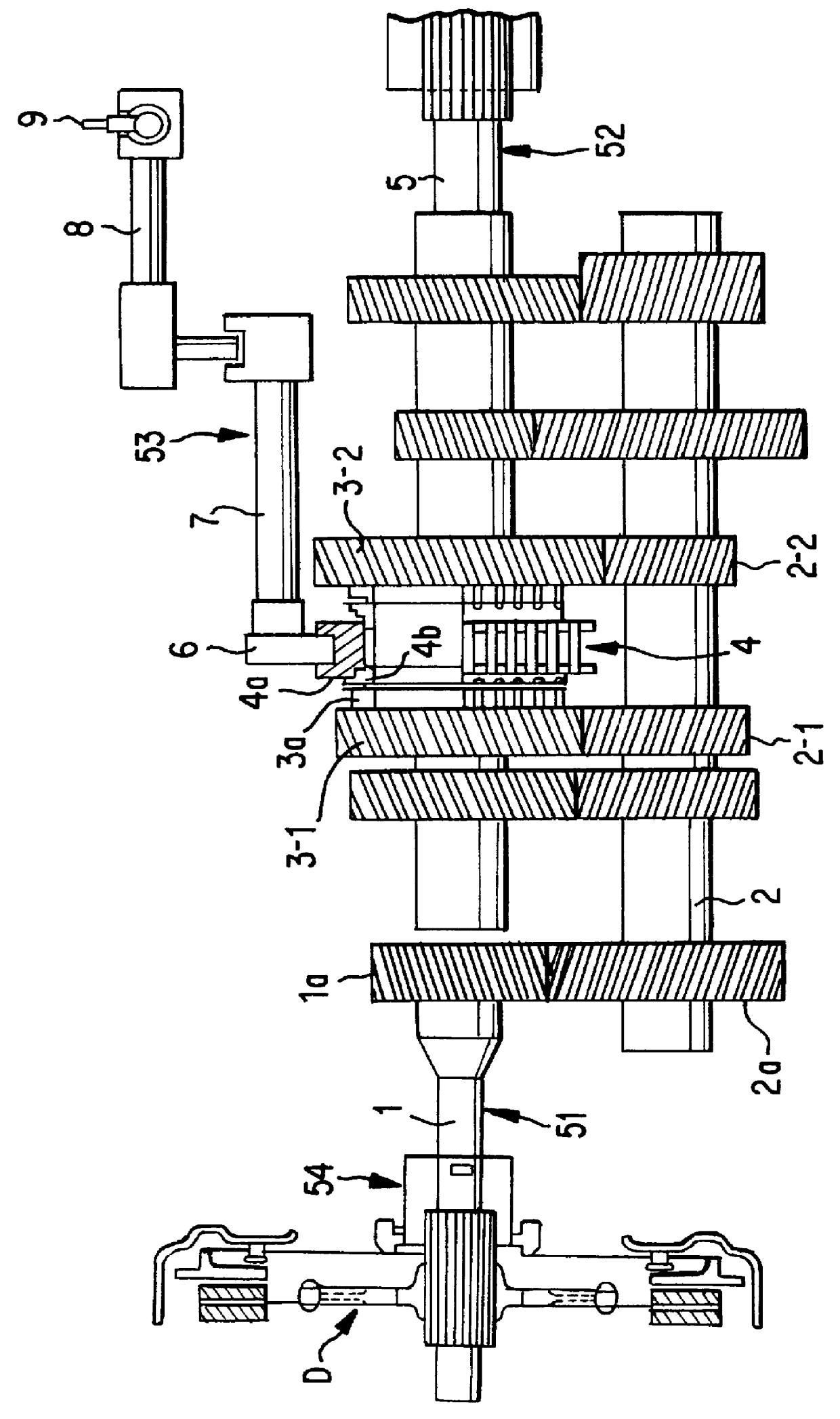
Generally, in order to change a shift in a speed changing apparatus (transmission), rotation of an input shaft (input rotation) connected to a clutch disc of an engine side and rotation of an output shaft (output rotation) of an driven wheel side should be coincided (synchronized). For this purpose, a synchromesh mechanism is used for transmitting rotation of an free-rotatable geardisposed around the output shaft to the output shaft smoothly. The synchromesh mechanism includes a synchronizer hub spline-mounted on the output shaft, a sleeve fitted on an outer peripheral surface of the synchronizer hub and having a groove with which a shift fork engages, and a synchronizer ring frictionally contacting with a cone surface of the free-rotatable gear by a shifting operation of the shift fork. The shift fork is driven by an operating load applied by an actuator of...
PUM
 Abstract
Description
Claims
Application Information