

Loop back clockspring having adhesive layer
a clockspring and adhesive layer technology, applied in the direction of cable arrangement between relatively moving parts, transportation and packaging, arrangement using a reel/drum, etc., can solve the problems of increasing the weight of the clockspring, the flatness of the ribbon cable, and the increase of the cost of manufacturing and inventorying the piece parts of such a clockspring
- Summary
- Abstract
- Description
- Claims
- Application Information
AI Technical Summary
Benefits of technology
Problems solved by technology
Method used
Image

Examples
first embodiment
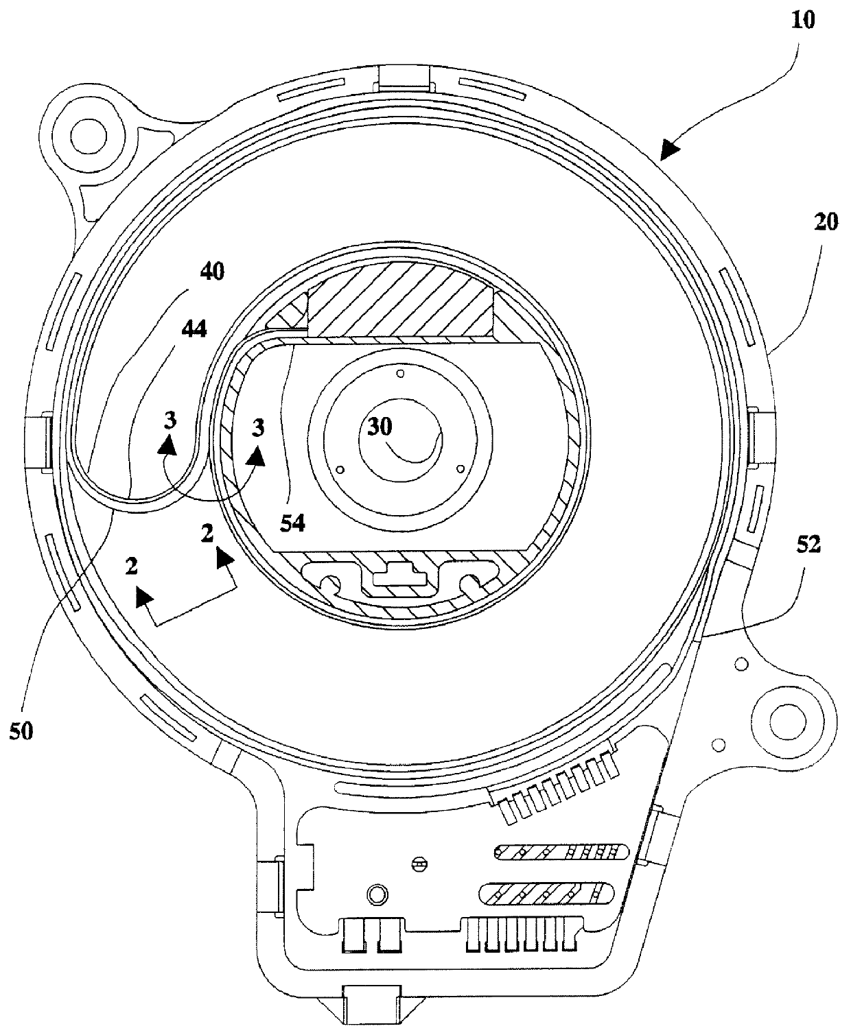
Referring now to the drawings, wherein like reference numerals designate identical or corresponding parts throughout the several views, and more particularly to FIGS. 1-2 thereof, the present invention is a rotary connector such as a clockspring 10 having a housing 20, a hub 30, and a flat ribbon cable 40. An adhesive element or retention element 50 is connected to the flat ribbon cable 40 along a majority of the length of the flat ribbon cable 40.
FIG. 1 is a cross-sectional, top view of the clockspring 10 with a cover (not shown) removed. A turned back portion 44 of the flat ribbon cable 40 clearly shows the adhesive element 50. A first end 52 of the adhesive element 50 is secured between the flat ribbon cable 40 and the housing 20, and a second end 54 of the adhesive element 50 is secured between the flat ribbon cable 40 and the hub 30.
FIG. 2 is a side view of the flat ribbon cable taken along line 2--2 of FIG. 1. FIG. 2 shows that the adhesive element 50 is applied only to a smal...
second embodiment
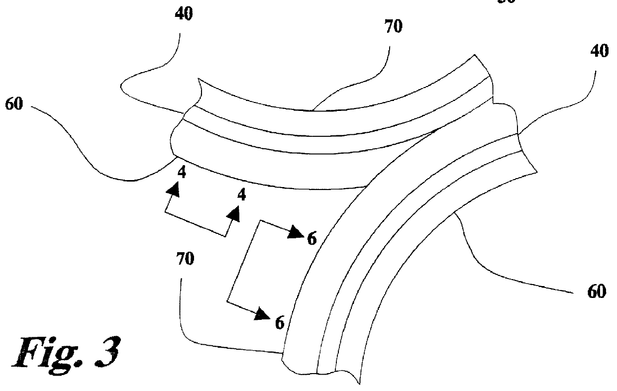
Another embodiment of the invention is shown in FIG. 3. FIG. 3 is a side view of the invention taken along a line similar to line 3--3 of FIG. 1. FIG. 3 shows a tongue layer 60 attached to a first surface of the flat ribbon cable 40, and a groove surface 70 attached to another surface of the flat ribbon cable 40 which forms an interlocking structure.
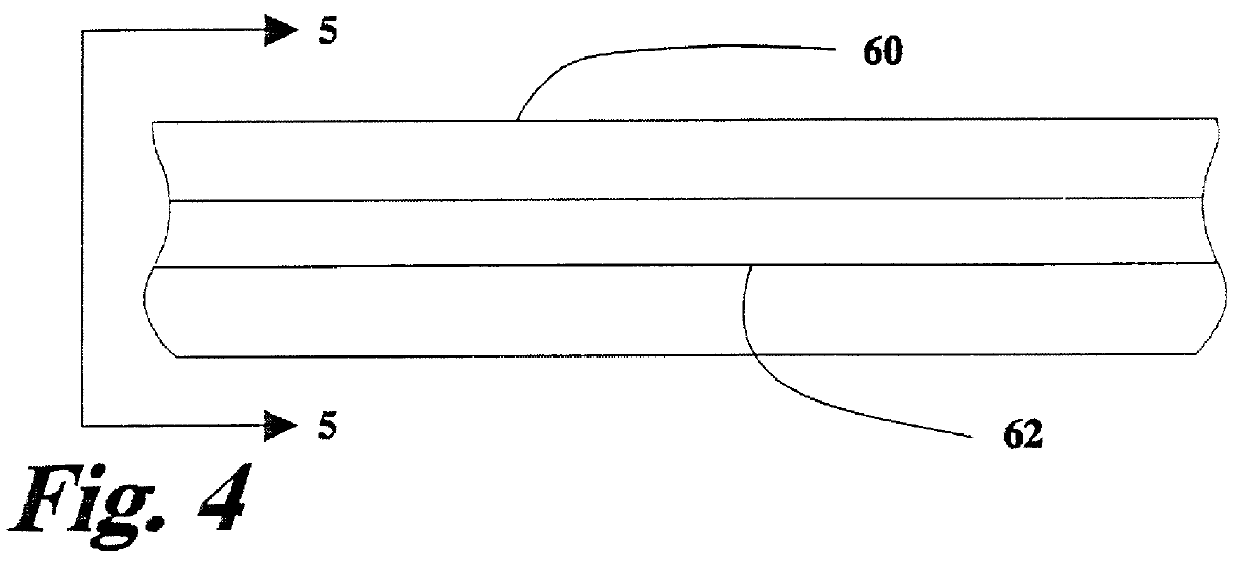
FIG. 4 is a side view of one surface of the flat ribbon cable showing the tongue layer 60. FIG. 5 is a cross-section view of the embodiment showing flat ribbon cable 40, the tongue layer 60, and the groove layer 70. The tongue layer 60 has a tongue 62 protruding from the tongue layer 60. The tongue layer 60 can be connected to or formed as part of the flat ribbon cable 40.
FIG. 6 is a side view of the other surface of the flat ribbon cable showing the groove surface 70. FIG. 7 is a cross-section view of the embodiment showing flat ribbon cable 40, the tongue layer 60, and the groove layer 70. The groove layer 70 has a groove 72 formed the...
fourth embodiment
A fourth embodiment of the invention is shown in FIG. 8. FIG. 8 is a side view of the invention taken along a line similar to line 3--3 of FIG. 1. FIG. 8 shows a hook and loop type of fastening or interlocking system. A first surface of the flat ribbon cable 40 has hooks 80 attached thereto, and a second surface of the flat ribbon cable 40 has loops 90 attached thereto. When the hooks 80 come into contact with the loops 90, the hooks 80 and loops 90 become locked together, thus securing the flat ribbon cable 40. The hooks 80 and loops 90 come out of engagement with each other when the two adjacent sections of flat ribbon cable are separated from each other. The operation of the clockspring is the same as discussed above.
In further embodiments, the invention previously discussed may be incorporated into other rotary connectors such as a retractable seat belt airbag connection device. This is important since airbags are being incorporated into the seat belt harness. To accommodate pas...
PUM
 Abstract
Description
Claims
Application Information