Anhydrous ammonia application device

an ammonia application device and anhydrous ammonia technology, applied in the direction of direct liquid fertiliser delivery, liquid fertiliser distribution, agriculture, etc., can solve the problems of increasing the cost of production for farmers, increasing environmental risks from water run-off, and the shortcomings of the applicator are still large enough to be problematic for users

Inactive Publication Date: 2001-01-02
KIMBERLY KEVIN H +1
View PDF12 Cites 6 Cited by
  • Summary
  • Abstract
  • Description
  • Claims
  • Application Information

AI Technical Summary

Benefits of technology

The embodiment of this invention results in advantages not provided by ammonia injectors disclosed in the prior art. The principal advantages of the present invention are that the injector tube provides a smoother and less obstructed conduit through which the ammonia is transported which increases regularity of flow and reduces pressure required; the precisely formed passage means affords far more uniform and accurate means of delivery of the ammonia to the soil; the end cap eliminates leaks and results in increased uniformity of delivery of ammonia across the whole anhydrous applicator, reduces plugging, and extends the lifetime of the injectors.

Problems solved by technology

Not only does this increase the costs of production for the farmer, but increases environmental risks from water run-off as well.
Without precise delivery of the ammonia by the injectors, the shortcomings of the applicator are still great enough to be problematic to the user.
It is thought that the relative lack of attention to modifying the ammonia injectors is due to the assumption that modification would yield only minimal improvement.
This assumption, in turn, is probably due to the temperature and pressure sensitivity of the anhydrous ammonia which function as obstacles to effectively applying the ammonia.
A myriad of problems are presented by this design.
First, as the ammonia enters the injector, the lip of the sheared end creates turbulence.
Second, the unevenly crimped and angled shape creates substantial turbulence and, consequently, the need for higher pressure to get enough ammonia through the tube for proper adherence to the soil.
This pressure at the point of injection, in turn, creates some compaction of soil as the ammonia hits it and reduces the degree of penetration of the ammonia into the soil.
If the delivery end is open or is crimped but not sealed, it often becomes plugged with dirt or mud during use; also, if the end is crimped but not completely sealed, it leaks.
The leak of one ammonia injector can be much greater than another since the degree of crimping is not uniform.
If there are holes near the delivery end of the injector, they are often not precisely drilled creating yet another opportunity for imprecise application.
Lastly, the prior art discloses ammonia injectors that must be replaced rather quickly because of wear created by dragging through the soil.
The combination of these factors wreak havoc on a farmer's calculations for nitrogen application, and, in turn, negatively effect his bottom line and our environmental health.

Method used


Image

  • Anhydrous ammonia application device
  • Anhydrous ammonia application device
  • Anhydrous ammonia application device

Examples


Embodiment Construction

)

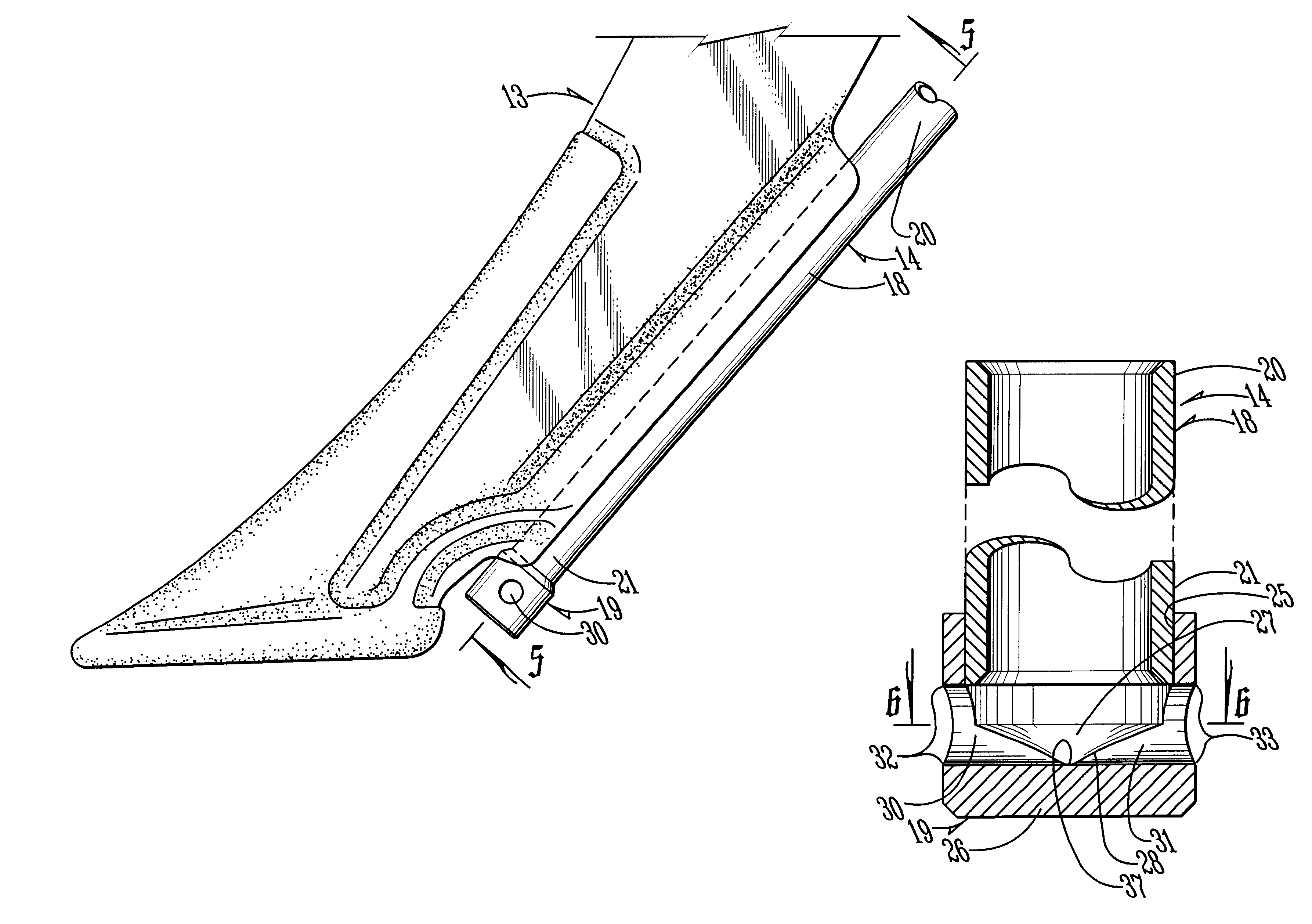
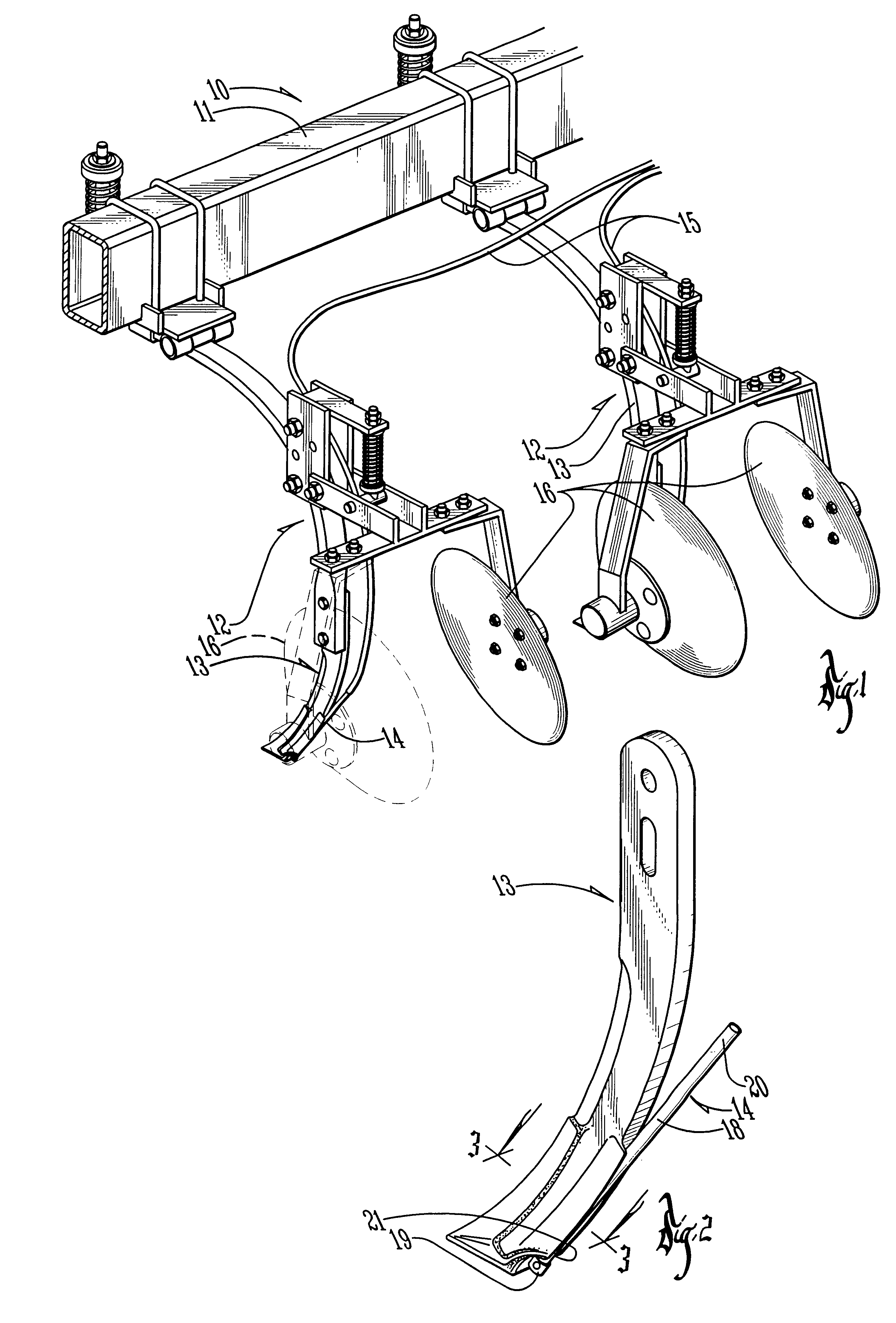
Shown by FIG. 1 is a portion of an apparatus 10 that represents a preferred embodiment of the present invention and is used to apply anhydrous ammonia to agricultural crop production land. The apparatus 10 includes a tool bar 11 and a plurality of injector assemblies 12. Each of the injector assemblies 12 includes generally a knife 13 and an injector 14 that is mounted on the rear of the knife 13, as best shown in FIGS. 2 and 4. As those skilled in the art will be aware, hoses 15 are attached to the injectors 14 to convey anhydrous ammonia from a manifold or other means of ammonia distribution to the injectors. The knives 13 are employed to break open the soil as the tool bar 11 travels over a field to permit the injection of the anhydrous ammonia therein. Each of the knives 13 is disposed between a pair of discs 16 that act to cover over with soil the applied ammonia.

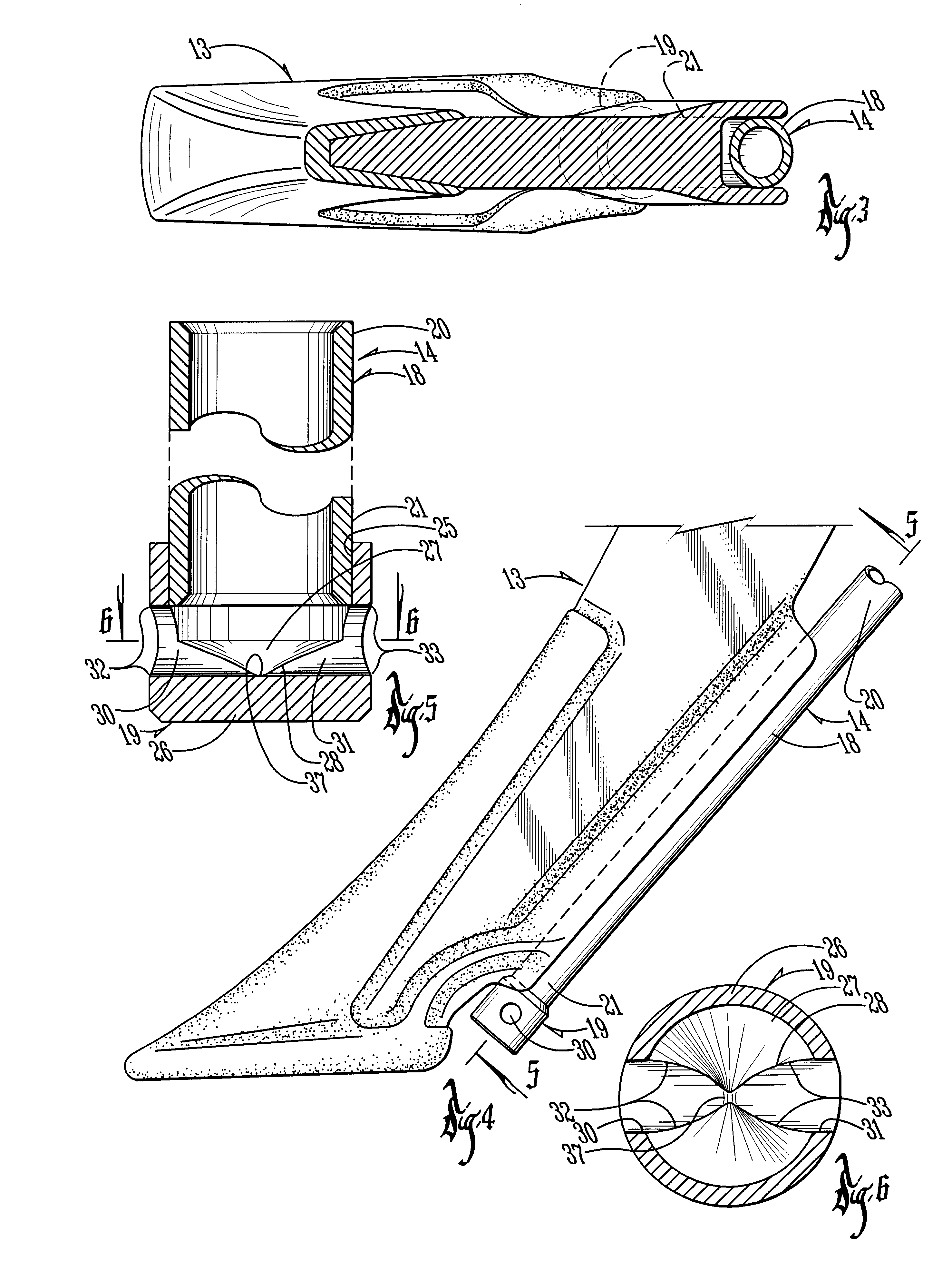
Referring now to FIGS. 4 and 5, each of the injectors 14 is preferably of a straight construction and is formed of ...


PUM


Abstract

An application device used to deliver anhydrous ammonia gas from the manifold on an applicator to the soil and including an ammonia injector. The ammonia injector consists of a smooth, metallic tube capped on one end by a metallic cap which is a precisely hollowed out metal shaft. The ammonia is applied through bores precision-drilled in the cap. The components of the ammonia injector greatly increase the accuracy with which the anhydrous ammonia can be applied, reduce the pressure at which the ammonia must flow through the injectors resulting in better and more even distribution in the soil, and increase the useful life of the injector.

Description

1. Field of the InventionThe invention relates in general to chemical applicators for agronomic purposes, and more particularly, to applicators pulled by motorized conveyance across crop production land for injecting anhydrous ammonia gas or liquid into the soil. The anhydrous ammonia is delivered in the form of a gas or liquid and replaces nitrogen that is essential for plant growth.2. Description of the Prior ArtSince the 1960's, the application of anhydrous ammonia to crop production land between growing seasons has been used to replace essential nitrogen in the soil. The process typically requires a pressurized tank of the anhydrous ammonia in liquid form attached to an applicator which injects the anhydrous ammonia into the soil in gaseous or liquid form. The tank and applicator are trailed over the soil to which the anhydrous ammonia is applied. There, until the soil warms, the nitrogen remains in a relatively stable compound. In the spring, as the soil warms and the fields ar...

Claims


Application Information

Patent Timeline
Patent Type & Authority Patents(United States)
IPC IPC(8): A01C23/00A01C23/02
CPCA01C23/024
Inventor KIMBERLY, KEVIN H.GEISLER, DARRELL K.
Owner KIMBERLY KEVIN H
Why Eureka
Try Eureka