Device for positioning a measuring sensor

a technology for positioning sensors and measuring sensors, which is applied in the direction of ac/dc measuring bridges, program control, instruments, etc., can solve the problems of difficult to precisely and quickly adjust such a probe to the local measuring position, suffer from repositioning accuracy, and difficulty in precise positioning. , to achieve the effect of quick and precise positioning, small structural and equipping effor

Inactive Publication Date: 2001-01-09
MOTOREN UND TURBINEN UNION MUNCHEN GMBH
View PDF8 Cites 19 Cited by
  • Summary
  • Abstract
  • Description
  • Claims
  • Application Information

AI Technical Summary

Benefits of technology

The invention has for its object to propose an apparatus with which a flow measuring probe of the described type can be qu

Problems solved by technology

In this context it is difficult to adjust such a probe exactly and quickly to the local measuring position, especially in the context of a zero point compensation relative to the lengthwise axis of the test pipe or housing.
Besides time consuming and complicated positioning and adjusting processes, the possibility of errors is particularly large in connection with relatively large pipe radii, and is predominantly b

Method used


Image

  • Device for positioning a measuring sensor
  • Device for positioning a measuring sensor
  • Device for positioning a measuring sensor

Examples


Embodiment Construction

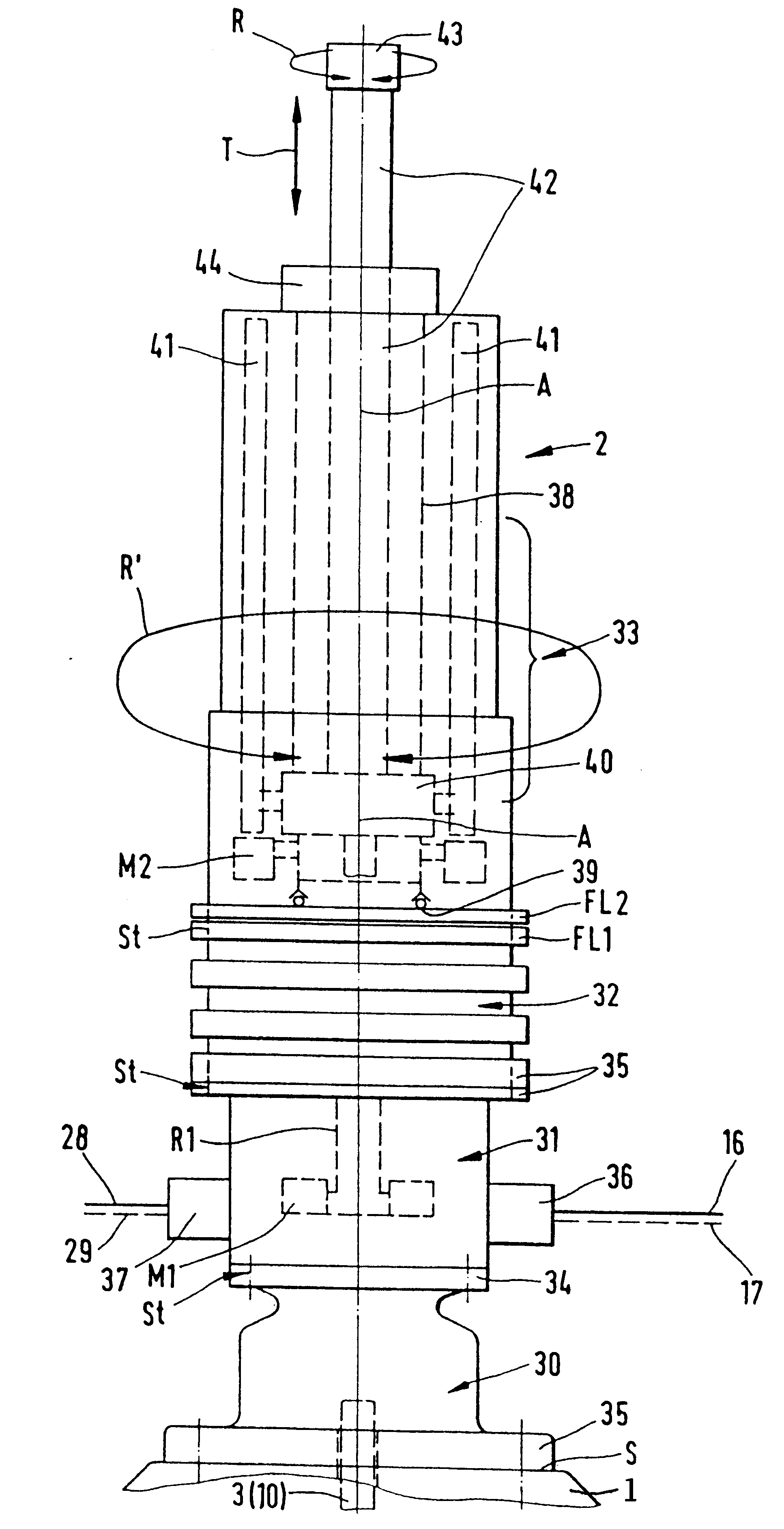
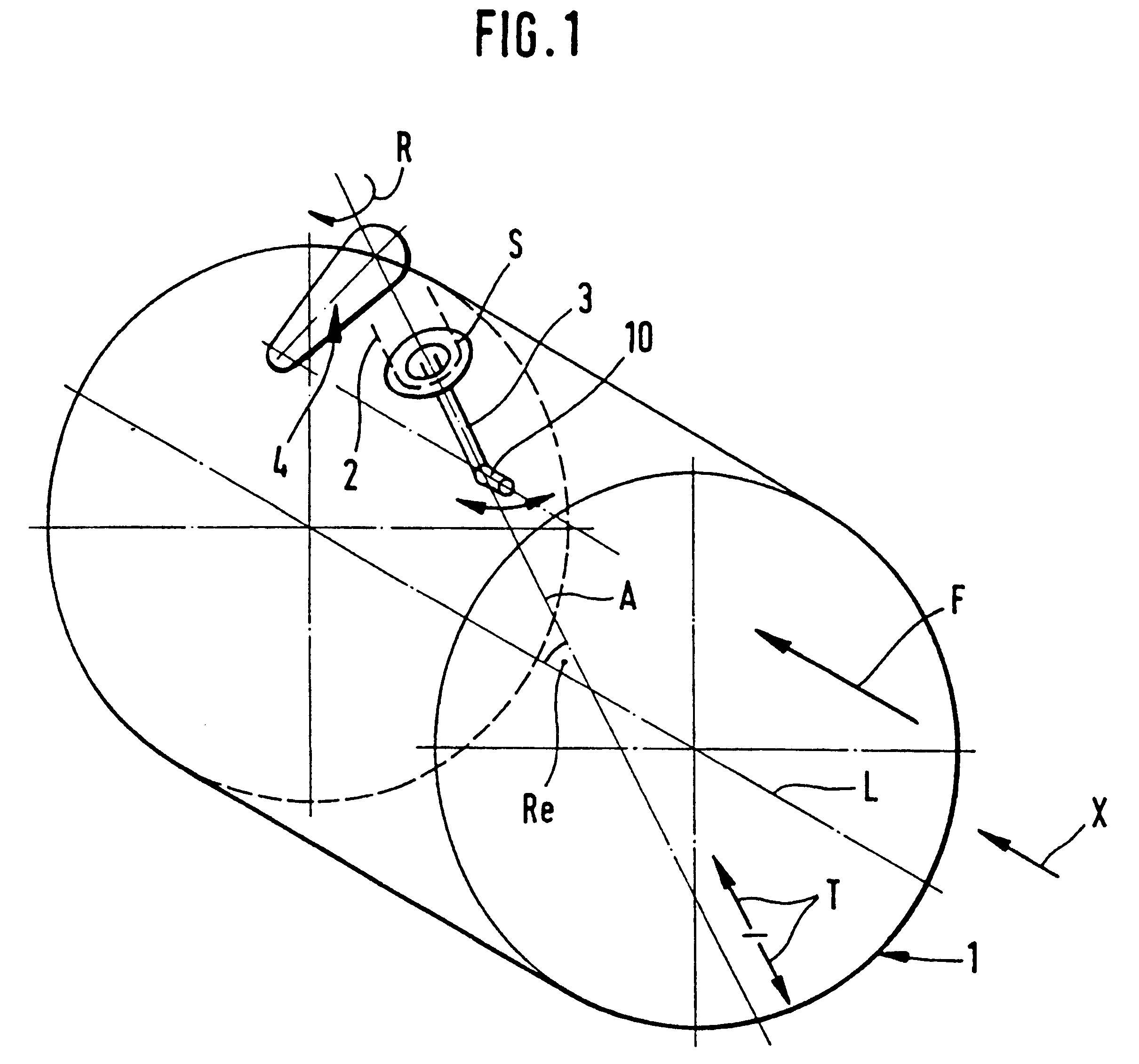
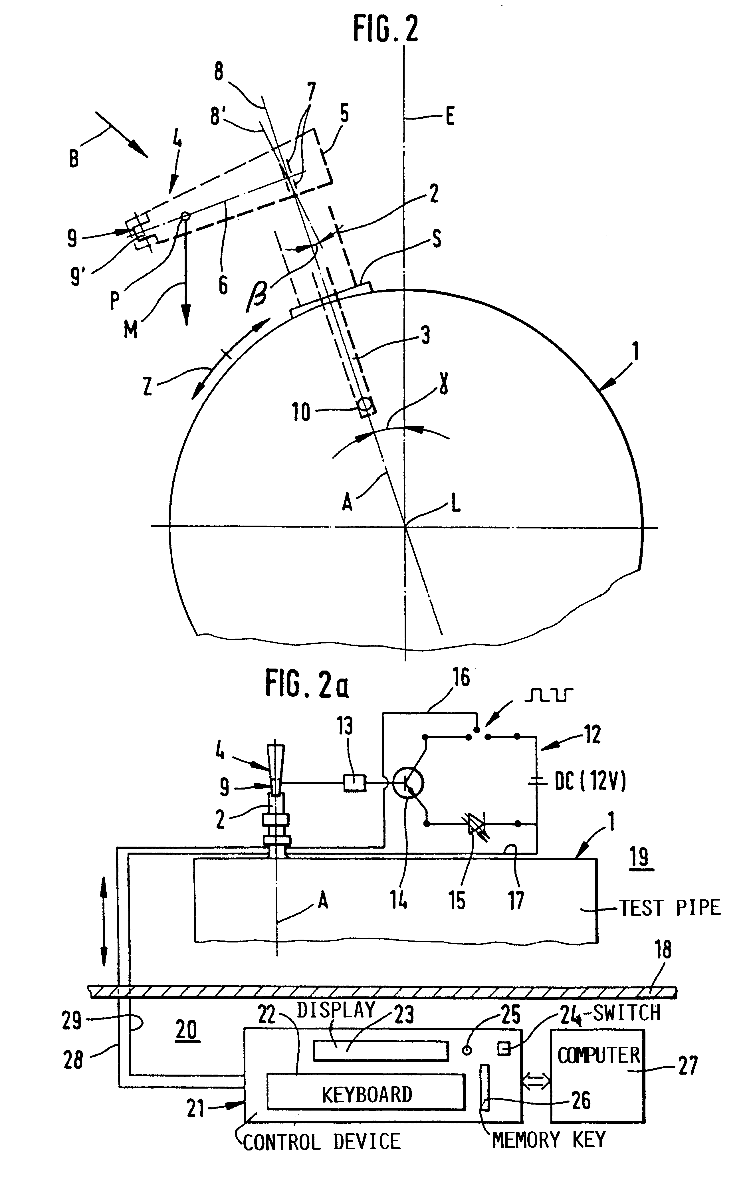
The invention may, for example, be carried out on a cylindrical test pipe 1 with a straight lengthwise axis L shown in FIG. 1. A probe positioning device 2 is connected to the test pipe 1 at a prepared circumferential location S in a flange-like manner. The probe adjusting device 2 will be described below in greater detail. A flow measuring probe 3 is coaxially mounted to the probe adjusting device 2. The probe adjusting device 2 includes suitable drive means such as motors, drive transmissions, threaded roller spindles, guide carriages, etc. in order to drive the measuring probe 3 in a translational stroke movement T in the direction of its lengthwise axis A and / or a rotational movement R about its lengthwise axis A.

In order to reposition the probe 3 translationally (T) or rotationally (R) in a direction toward the required measuring position, between the inner wall circumference and the lengthwise axis L of the test pipe 1, a control arrangement is provided, which will be describe...


PUM


Abstract

The device is constructed to position a measuring sensor, especially a sensor head at an angle to a sensor shaft, precisely at the point of measurement and in the direction of a fluid flowing in a test tube, in which there is an adjuster through which the measuring sensor, in a coaxial arrangement, can be adjusted via a first adjusting motor about its axis and/or by a second adjusting motor along its axis. A control device communicates with an electronic computer for controlling the sensor adjustment. An adjuster (4) is coupled to the sensor to rotate in unison therewith and has a rotatable pendulum which, in the position of rest transversely to the test tube axis defines the zero position of the sensor. Limit positions of the pendulum are predetermined from a relative movement of the adjuster about the axis which can be photometrically converted into position signals. The computer mathematically halves the angular adjustment calculated from the position signals received and sets the adjuster with the sensor to mechanical zero by the respective positioning stop command signals.

Description

CROSS-REFERENCE TO RELATED APPLICATIONS:Not Applicable.FEDERALLY SPONSORED RESEARCH AND DEVELOPMENTNot ApplicableMICROFICHE APPENDIXNot ApplicableThe invention relates to an apparatus for precisely aiming a measuring probe or a sensor head onto a location to be sensed or monitored in a test pipe with due regard for a fluid flow direction flowing through the test pipe.BACKGROUND INFORMATIONFor the purpose of testing individual components of a turbine engine, for example of a compressor, a turbine, or a combustion chamber, measuring probes or flow measuring probes are used. In this context, the measuring probes may be pressure, temperature, anemometer, or direction measuring probes, among others. The measurement is carried out in a pressurized air or hot gas flow, either directly on the engine or, for example on a cylinder pipe-type test specimen, by means of which existing process conditions or parameters, or process conditions or parameters to be varied, are simulated on a test stan...

Claims


Application Information

Patent Timeline
IPC IPC(8): G01P21/00G01P21/02G05D3/12G01P5/00G01P13/02G05B19/401
CPCG01P21/025G05D3/12
Inventor KERNER, LEANDER
Owner MOTOREN UND TURBINEN UNION MUNCHEN GMBH
Why Eureka
Try Eureka