Indicating light display having several light sources

a technology of light sources and light sources, applied in the direction of fixed installation, lighting and heating apparatus, lighting support devices, etc., can solve the problems of uneven illumination at junctions, transition zones, and inability to provide homogeneous light, and achieve the effect of large siz

Inactive Publication Date: 2001-01-09
VALEO VISION SA
View PDF7 Cites 44 Cited by
  • Summary
  • Abstract
  • Description
  • Claims
  • Application Information

AI Technical Summary

Benefits of technology

An object of the present invention is to overcome the above mentioned drawback, and to provide an indicating light display which may be made in a large size and which uses a plurality of light sources, while at the same time presenting a homogeneous illumination to the observer, which is of particular advantage from the aesthetic point of view.

Problems solved by technology

The first indicating light displays of the above type had the disadvantage that they did not provide a homogeneous light, despite various spreading arrangements for spreading the light which were used and which consisted generally of billets or toroids incorporated in the cover lens of the display, or in an optical plate of the display.
Although this disadvantage is in general tolerable from the point of view of the statutory regulations, it is ugly from the aesthetic point of view, especially since, nowadays, increasing importance is being attached to the homogeneity of the light emitted by indicating lights of vehicles.
However, in such an arrangement there would then be irregularities in the illumination at the junctions, or transition zones, between adjacent sub-assemblies.

Method used


Image

  • Indicating light display having several light sources
  • Indicating light display having several light sources
  • Indicating light display having several light sources

Examples


Embodiment Construction

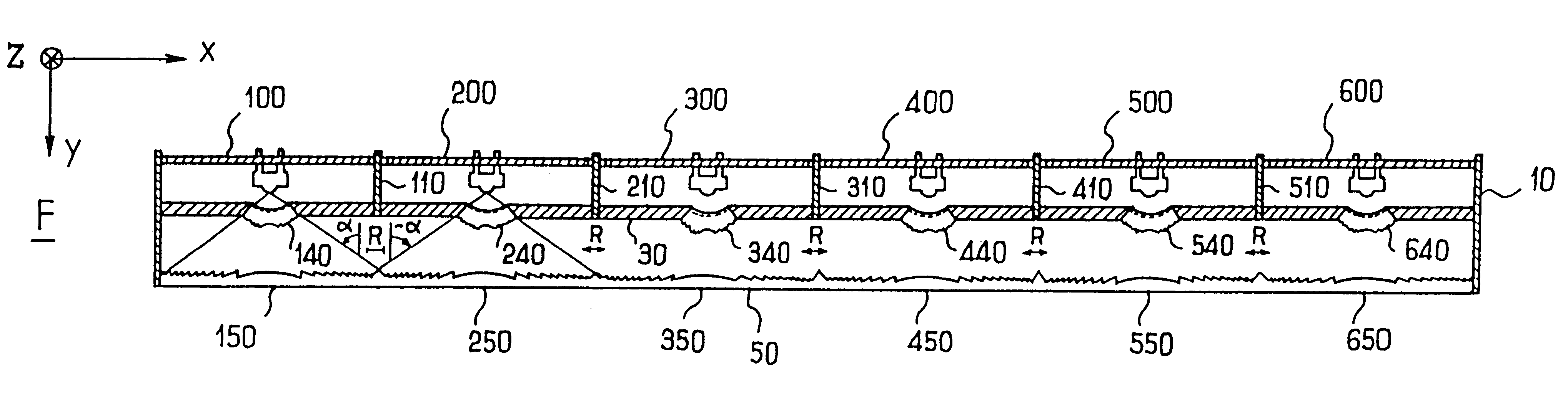
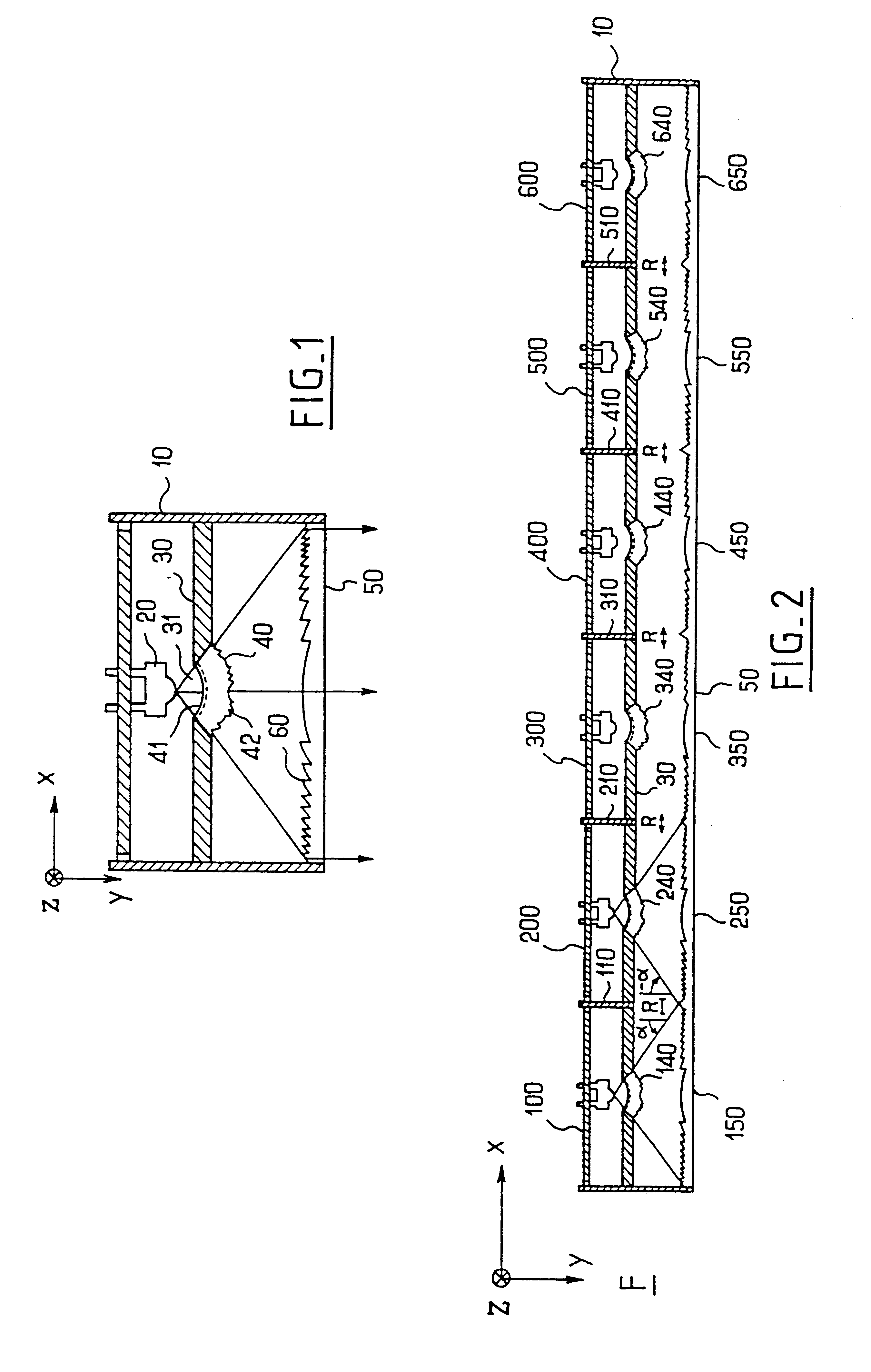
Before we proceed with the description, three orthogonal directions X, Y and Z will be defined. These directions will be used in the drawings and in the following description. Y is the direction of the optical axes of the elements of the indicating light displays shown in the drawings. X and Z are the horizontal and vertical directions, respectively, in the display as mounted in a vehicle.

Reference is first made to FIG. 1, which shows an optical cell comprising a housing 10, having a base on which a light source is mounted. This light source may for example be a so-called Brewster diode 20. An opaque wall 30 extends across the housing 10 within the latter, and has a central circular aperture 31. The aperture 31 is filled by a hemispherical lens 40 for spreading the light rays issued from the diode 20. This lens 40 is preferably made integral with the opaque wall 30, and has an inner face 41 which is striated, and an outer face 42 which is also striated. The cell includes a second pl...


PUM


Abstract

An indicating light display for a motor vehicle, and in particular a raised stop light in the form of a strip which contains a plurality of light sources, also includes optical processing means for redirecting the light received from the light sources so that it will be propagated in the general emission direction. The display thus consists of a series of light cells, each defining a transition zone between each cell and the next. The optical processing means include, in association with each light source, a first element for distributing the light, in a plane at right angles to the general emission direction, on a second element in the form of an optical plate. This optical plate is divided into zones each associated with one of the cells and formed with projecting striations. Each transition between a zone and the next zone is formed with a transition striation which receive light from both of the two adjacent light sources and redirects this towards the general emission direction.

Description

The present invention relates to indicating light displays for motor vehicles, applicable especially to light displays of the stop lamp type, that is to say brake lights which can be mounted inside the cabin of the vehicle and against the rear window of the vehicle, or else be integrated into thin components which are situated at the rear of the vehicle, such as fins or other aerodynamic elements.The first indicating light displays of the above type had the disadvantage that they did not provide a homogeneous light, despite various spreading arrangements for spreading the light which were used and which consisted generally of billets or toroids incorporated in the cover lens of the display, or in an optical plate of the display. Although this disadvantage is in general tolerable from the point of view of the statutory regulations, it is ugly from the aesthetic point of view, especially since, nowadays, increasing importance is being attached to the homogeneity of the light emitted b...

Claims


Application Information

Patent Timeline
Patent Type & Authority Patents(United States)
IPC IPC(8): B60Q1/26F21S8/10F21V5/00
CPCB60Q1/2696F21S48/215F21S48/2212F21S43/14F21S43/26
Inventor GODBILLON, VINCENT
Owner VALEO VISION SA
Why Eureka
Try Eureka