Wearable intravenous fluid heater

a technology of fluid heater and wearable body, which is applied in the direction of lighting and heating apparatus, contraceptive devices, instruments, etc., can solve the problems of fluid overheating, fluid may become overheated, and overheating can damage certain types of intravenously delivered fluids

Inactive Publication Date: 2001-01-16
BELMONT INSTR LLC
View PDF48 Cites 242 Cited by
  • Summary
  • Abstract
  • Description
  • Claims
  • Application Information

AI Technical Summary

Benefits of technology

The device of this embodiment of the present invention may also include an electrically insulating external housing and disposable cover for enclosing the aforesaid components of the device so as to prevent contamination of same and risk of electric shock injury to the patient wearing the device. The heat exchanger may be unattached to the remainder of the device and may be held in place in the device by forces applied to the exchanger by the mechanism used to lock the housing in place about the other components of the device. Advantageously, this permits both the cover and heat exchanger to be disposable / replaceable, and the remainder of the device to be reusable.
Thus, in accordance with the present invention, the entire intravenous fluid heater (i.e., the heat exchanger, heating element(s), sensors, controller, etc.) may be comprised within a single protective enclosure and dimensioned so as to be wearable adjacent the patient's infusion situs. The controller may be programmed to detect presence of reduced fluid flow and / or air in the fluid flow, and to warn and / or prevent further supply of the fluid upon detection of conditions. Additionally, the heating elements are completely solid, and no warming fluid is used to heat the infusion fluid. Advantageously, the above features provided in accordance with the present invention permit the present invention to overcome the aforesaid and other disadvantages of the '693 and '094 patents.

Problems solved by technology

Unfortunately, the heating device disclosed in the '693 patent suffers from several disadvantages.
First, since the heating elements of the '693 device apply non-uniform, graduated heating to the fluid traversing the flow path, the risk exists that, depending upon the fluid flow rate through the flow path, the fluid may become overheated (i.e., heated above the desired target temperature for infusion) at the portion of the heating elements applying elevated amounts of heat to the fluid.
If sufficiently elevated, such overheating can damage certain types of intravenously delivered fluids (e.g., blood and blood-products, if the overheating is above about 41 degrees C.).
Also, the heating device disclosed in the '693 patent is not wearable by the patient adjacent the fluid infusion situs.
Unfortunately, a significant proportion of intravenous fluid infusions take place at such low flow rates.
A yet further disadvantage of the '693 patent's heating arrangement is that although means are included for reducing gas bubble formation in the infusion fluid, no means are provided for automatically determining whether such bubbles are present in the fluid or whether there has been reduction in fluid flow rate, and for taking appropriate action (e.g., providing warning and / or stopping fluid flow into the patient) in the event such conditions are determined to be present.
As will be appreciated by those skilled in the art, if left unchecked these types of conditions can be, at minimum, deleterious to patient well-being, and at most, life-threatening.
An additional disadvantage of the heating device disclosed in the '639 patent results from its use of metal foil membranes.
Such spot heating can result in damage to the fluid being heated.
The warming fluid is supplied via fluid supply tubing to the box from a separate fluid source that is not dimensioned or suitable for being worn by the patient, such as a water heater.
Disadvantageously, use of a warming fluid / infusion fluid type of heat exchanger, and a warming fluid heater that is remote from the heat exchanger and not wearable by the patient, make '094 patent's arrangement bulky, and relatively difficult to move and set up for use.
Also disadvantageously, if even a single crack, pin-hole, imperfect seal, or other opening exists in the infusion fluid tubing / fittings in the heat exchanger, the infusion fluid may become contaminated with the warming fluid.
Unfortunately, the prior art disclosed in each of these patents suffers from the aforesaid and / or other disadvantages and drawbacks.

Method used


Image

  • Wearable intravenous fluid heater
  • Wearable intravenous fluid heater
  • Wearable intravenous fluid heater

Examples


Embodiment Construction

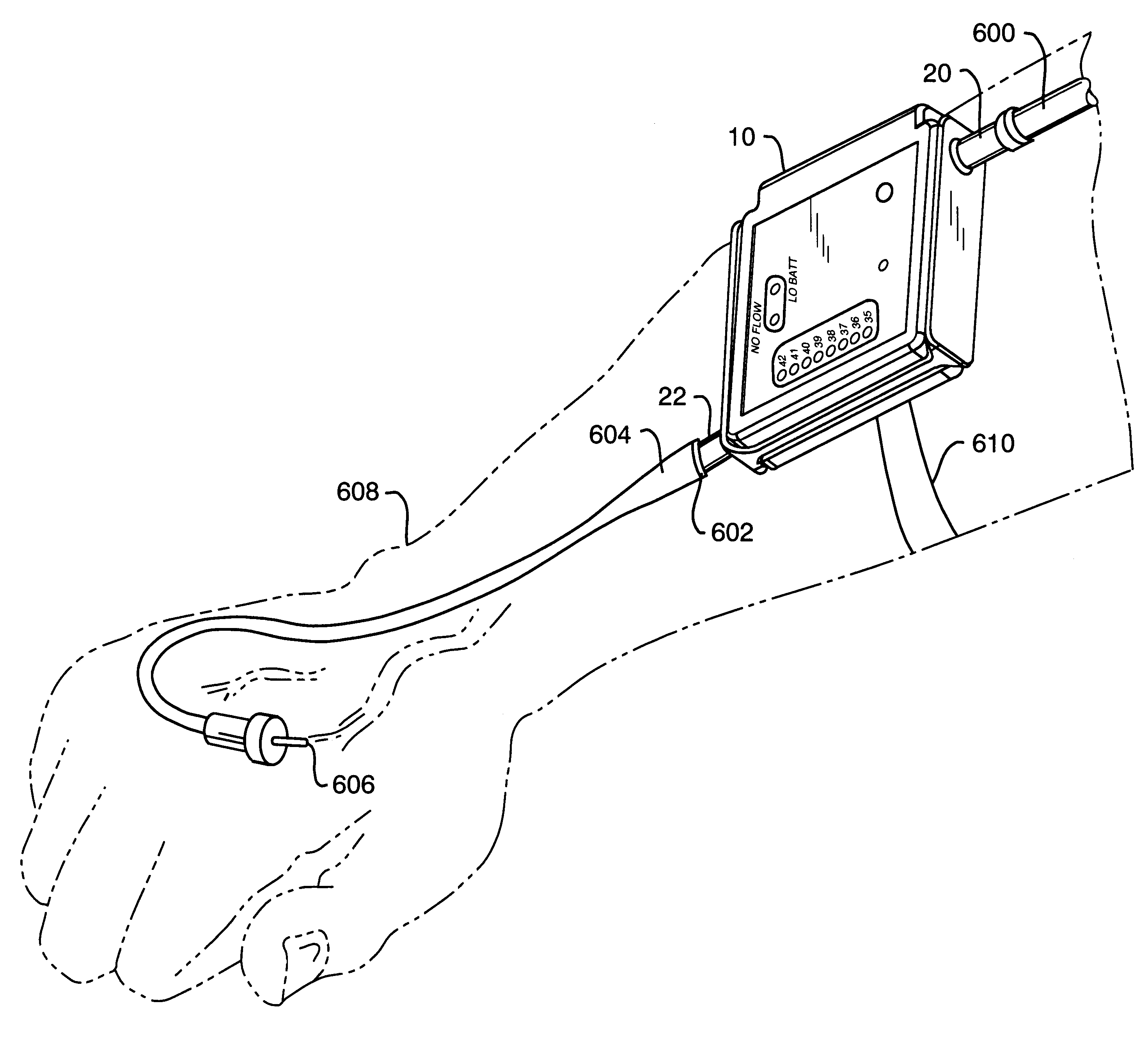
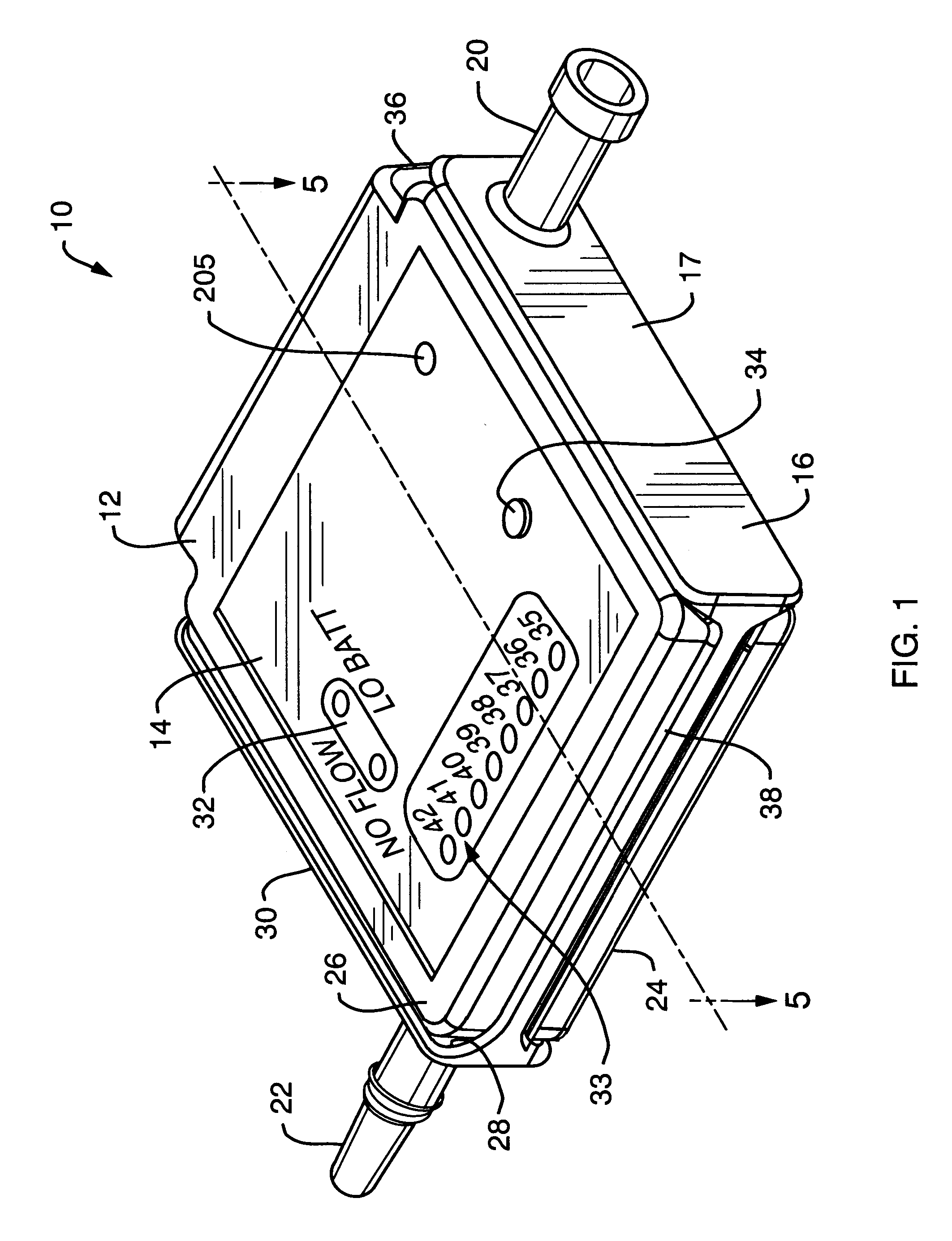
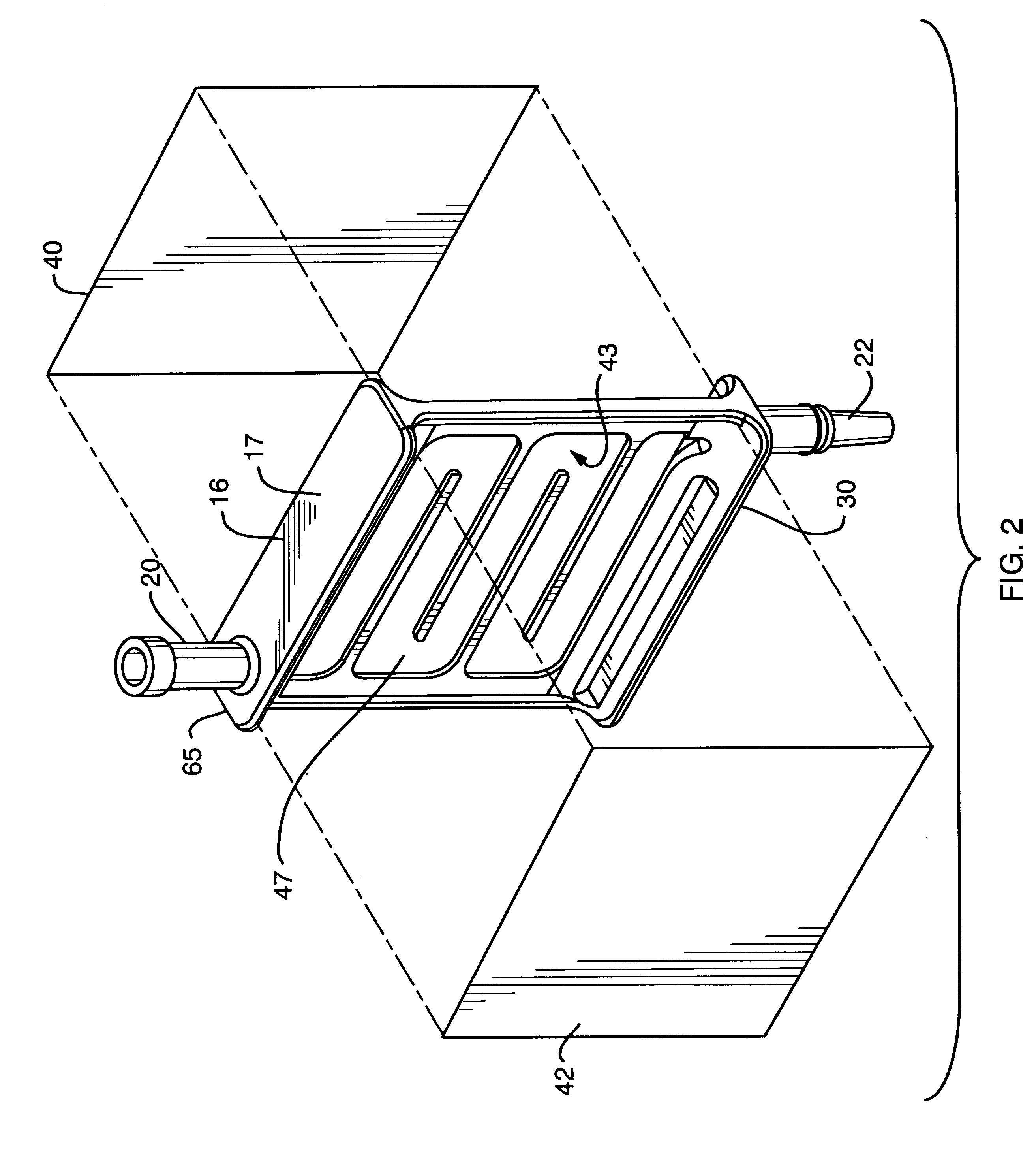
FIGS. 1-12A and 12B and 15 depict one preferred embodiment 10 of the wearable infusion fluid heater of the present invention. Heater 10 comprises a hard plastic housing 12 in the form of two generally square-shaped members 24, 26 joined via a locking hinge mechanism 36. Hinge mechanism 36 comprises an upper hinge portion 37 and mating lower hinge portion 39. These hinge portions 37, 39 are pivotably connected to each other via conventional means (e.g., a bolt, screw, or similar means, not shown) fastened into the common opening through the portions 37, 39 formed when the portions 37, 39 are mated with each other and the respective openings 41,43 of the portions 37, 39 are in coaxial alignment with each other. Openings 41,43 extend longitudinally through the hinge portions 37, 39.

A rectangular indicator face plate 14 is slightly undersized relative to rectangular recessed area 57 of top plate 26 and is attached there at via conventional means (e.g., glue or other type of bonding mate...


PUM


Abstract

An intravenous fluid heater is provided that is dimensioned so as to be wearable adjacent a patient's intravenous fluid infusion situs. In one embodiment, the heater includes a heat exchanger for defining a flow path through the heater for fluid to be infused via the infusion situs. At least one controllable heating element is provided for heating the fluid in the flow path by heat conduction thereto through the heat exchanger. Sensors are included for sensing respective temperatures of entering and exiting fluids of the flow path. A controller controls, based upon the temperatures of the exiting fluids, heating of the fluid in the flow path by the heating element so as to cause the fluid in the flow path to be substantially uniformly heated to a desired infusion temperature prior to exiting the heater.

Description

1. Field of the InventionThe present invention relates generally to a device for heating to a desired infusion temperature a fluid to be supplied intravenously to a patient. More specifically, it relates to such a device that is (1) dimensioned to be wearable on the patient adjacent to the infusion situs (i.e., the location on the patient's body were the fluid is to be infused into the patient), and (2) configured to determine automatically when, and to provide warning if, the fluid flow rate in the device falls below a desired minimum threshold therefor, and / or gas (e.g., air) is present in the fluid. Although the present invention finds particular utility in heating of fluids which are to be supplied intravenously at relatively low flow rates (e.g., below about 2550 ml / hour for fluids to be heated to an infusion temperature of between 38-42 degrees C. from an input temperature into the device of 10 degrees C., or below about 3600 ml / hour for fluids to be heated to such an infusion...

Claims


Application Information

Patent Timeline
Patent Type & Authority Patents(United States)
IPC IPC(8): A61M5/44A61M5/36A61M5/168
CPCA61M5/365A61M5/44A61M5/16886A61M2205/3331
Inventor CASSIDY, DAVIDHART, RUSSELL
Owner BELMONT INSTR LLC
Why Eureka
Try Eureka