Boat bottom hull design

a bottom hull and hull technology, applied in vessel construction, special-purpose vessels, transportation and packaging, etc., can solve the problems of excessive surface area and its accompanying excessive drag, ineffective use of relatively small "flow trips" and other problems, to achieve the effect of effectively exploiting the potential advantages of internal chines

Inactive Publication Date: 2001-01-23
HALTER HAROLD P
View PDF3 Cites 23 Cited by
  • Summary
  • Abstract
  • Description
  • Claims
  • Application Information

AI Technical Summary

Benefits of technology

The present invention over-comes the prior art's deficiencies by, in part, using a boat bottom hull with a much deeper, transverse step, as shown in FIG. 3 in comparison to, for example, FIG. 2, to more effectively exploit the potential advantages of internal chines and lifting strakes. Thus, in the present invention, the hull bottom has a much deeper transverse step which effectively achieves a bi-modal hull form--displacement and planing.
In addition and in combination with the deeper transverse step, the concave curvature of the narrow planing region of the hull shifts the center of dynamic pressure forward and provides a more balanced acceleration, with less extreme boat attitudes, in the transition from displacement to planing mode, as well as when operating at steady speeds over the entire speed range.
It is a further object of the invention to provide a planing boat hull that consistently achieves and maintains the flow separation needed to assure the relatively low surface area needed for minimum planing resistance and minimum sea wave impact acceleration.
It is a further object of the invention to provide a planing boat hull that utilizes the concave curvature of the narrow planing region of the hull to shift the center of dynamic pressure forward, providing a more balanced acceleration, with less extreme boat attitudes, in the transition from displacement to planing mode, as well as when operating at steady speeds over the entire speed range.
It is also a secondary object of the invention to provide a boat hull that is able to ride on less wetted surface, thereby reducing power requirements, fuel costs, and increasing potential speed.

Problems solved by technology

The conflict is that, in order to have the area needed for displacement operation, excessive area and its accompanying excessive drag tend to occur in high speed planing operation.
In the current state-of-the-art of internal chines and lifting strakes, relatively small "flow trips" are used that are often not effective.
The main shortcoming is that the flow separated at the chine, or strake, can reattach, and thus the prior art has not consistently achieved the relatively low wetted surface area needed for optimum planing performance.

Method used


Image

  • Boat bottom hull design
  • Boat bottom hull design
  • Boat bottom hull design

Examples


Embodiment Construction

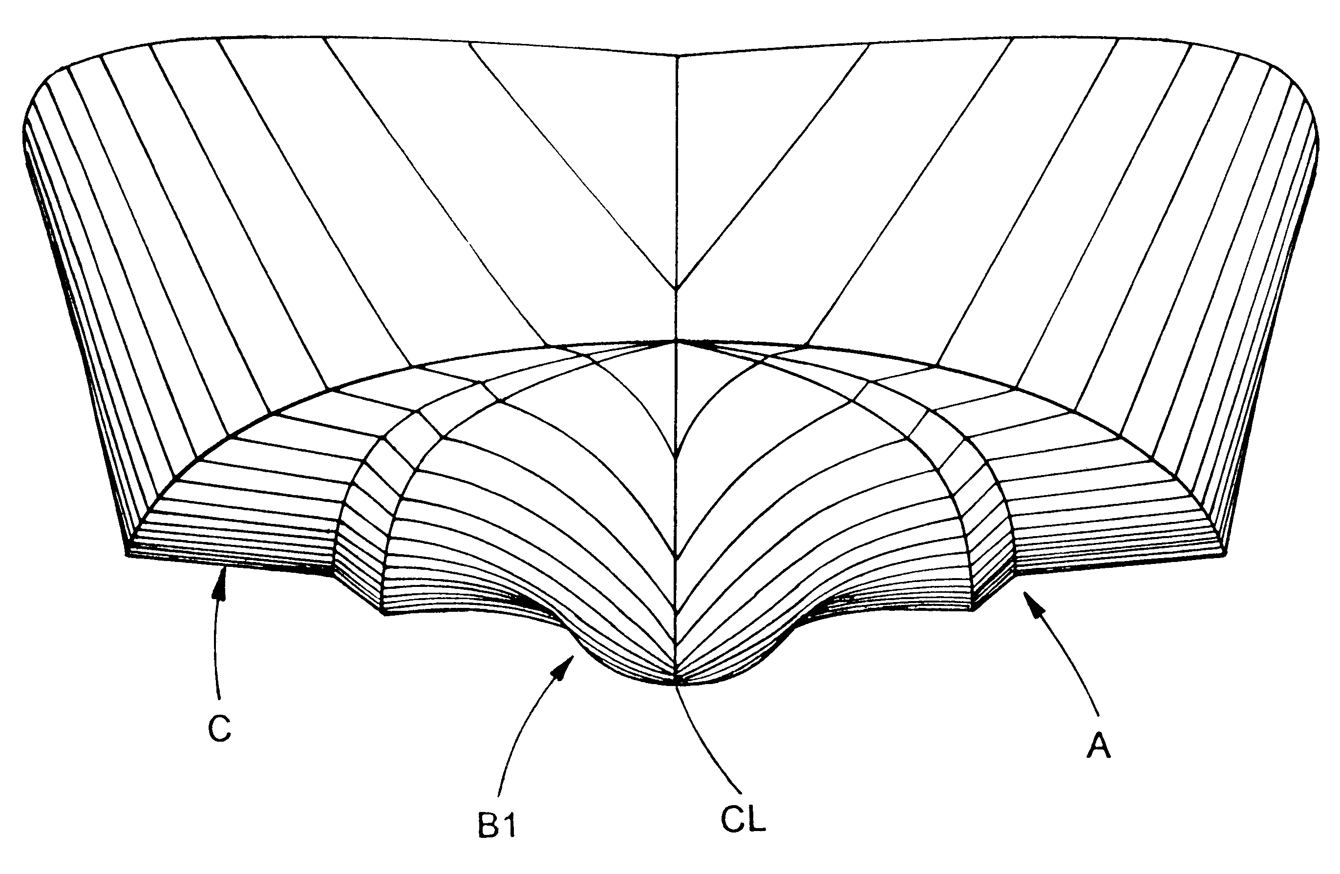
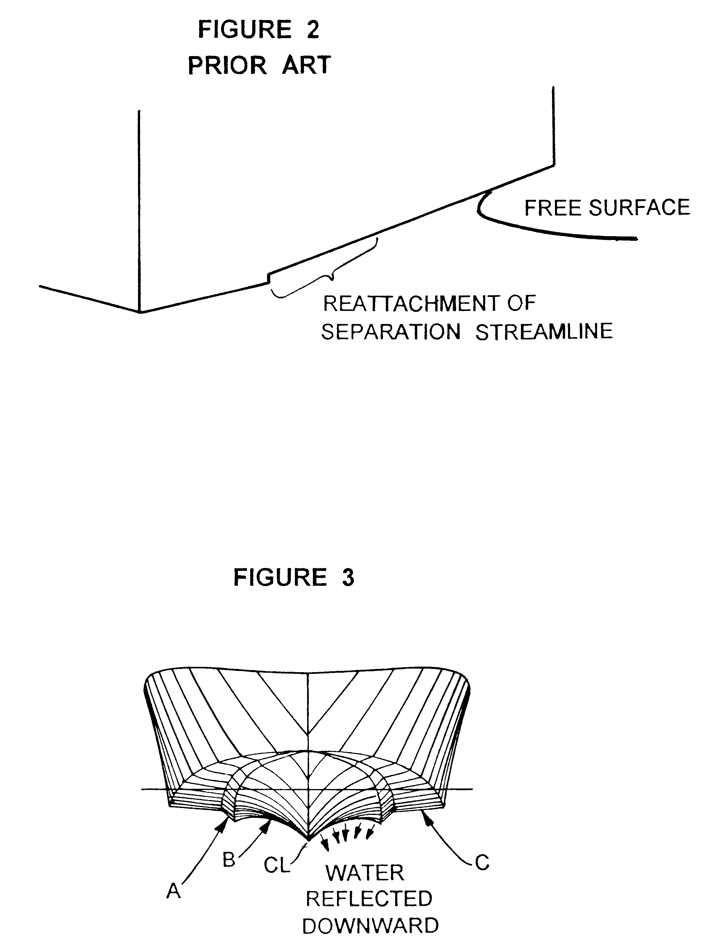
As shown in FIG. 3, the exemplary boat hull design of the present invention is comprised of three essential features--a stepped inboard chine A, a concave centerline section B, and an outboard flat of the bottom C.

The stepped inboard chine A directs the water away from the hull and is considerably larger or deeper than conventional chines. The depth of the chine ensures that the outboard flat of the bottom generally remains out of the water.

The concave centerline section B directs the water both away and down from the hull, causing an upward resultant force. The arrows in FIG. 3 indicate the direction of the deflected water which is normal to the surface of the hull. The result is to increase the upward force which supports the hull. This allows the hull to be supported by an even smaller area and therefore reduces the drag, while allowing the boat to plane at slower speeds.

The outboard flat of the bottom C acts as reserve buoyancy at lower speeds and gives transverse stability in a...


PUM


Abstract

A hull design with a maximally narrowed lower hull comprised of a stepped inboard chine and a concave centerline section resulting in the center of buoyancy and center of gravity preferably being in the same longitudinal position. The narrow lower hull optimally reduces the wetted surface area required, thereby reducing power requirements, fuel costs, and increasing speed potential. Exemplary dimensions for a forty-five (45') foot hull are disclosed. The hull has a much deeper transverse step (note FIG. 3) to more effectively exploit the potential advantages of internal chines and lifting strakes, which deeper transverse step effectively achieves a bi-modal hull form-displacement and planing. The hull form consistently achieves and maintains the flow separation needed to assure the low surface area needed for minimum planing resistance and minimum sea wave impact acceleration. Additionally, the hull's convex curvature in the narrow planing region of the hull shifts the center of dynamic pressure forward, providing a more balanced acceleration, with less extreme boat attitudes, in the transition from displacement to planing mode, as well as when operating at steady speeds over the entire speed range.

Description

The present invention relates to a planing boat hull design, and more particularly to a boat hull bottom design that provides improved performance, from the standpoints of both (1) higher speed for a given installed power, and (2) reduced impact acceleration in waves for a given speed.Planing refers to the hydrodynamic process whereas, on increasing speed, the boat is lifted up relative to the water surface by dynamic pressure acting over the surface of the boat hull bottom. This dynamic pressure is an increasing function of boat speed. At rest, the boat is supported (floats) by pressure provided by hydrostatics at zero speed, resulting in the boat being positioned deeper in the water, displacing a larger water volume than in planning.Conflicting conditions of operation therefore exist with the typical planning craft:1. displacement (low speed) mode, requiring relatively large displaced volume and larger wetted surface area, and2. planing (high speed) mode, requiring relatively smal...

Claims


Application Information

Patent Timeline
Patent Type & Authority Patents(United States)
IPC IPC(8): B63B1/04B63B1/00
CPCB63B1/04B63B1/18B63B2001/201
Inventor HALTER, HAROLD P.
Owner HALTER HAROLD P
Why Eureka
Try Eureka