
Curved surface, real image dome display system, using laser-based rear projection

a technology of real image dome and display system, which is applied in the field of real-time, curved surface imaging system, can solve the problems of severe limitations on training device location and configuration, restricting the number of projectors, and restricting the placement and movement of viewers

Inactive Publication Date: 2001-01-23
RAYTHEON CO
View PDF5 Cites 102 Cited by
  • Summary
  • Abstract
  • Description
  • Claims
  • Application Information

AI Technical Summary

Problems solved by technology

On conventional front projection spherical dome displays, it is often necessary to use elaborate mounting mechanisms and costly optical lens arrangements to insure a collect viewing perspective, without interfering with the projected light path.
Because the projector and projected light rays are on the same side of the screen as the viewer, physical limitations are imposed which restrict placement and movement of the viewer.
When employed in simulation and training systems, the necessity for avoiding occluding projected light rays places severe limitations on training device location and configuration.
In domed imaging systems which employ multiple front projectors, the physical limitations may also undesirably restrict the number of projectors and, as a result, the number of images that the system can employ.
This can result in irregularities being visible on the display surface, such as mottling.
Producing dome screens with these desired optical characteristics is an expensive process requiring specialized talent to produce the required finish.
Another factor which contributes to the complexity and cost of front projection domed imaging systems is the distortions caused by off-axis projection of images onto the curved dome surfaces.
This can increase the cost of the system and require a significant amount of time.
In actuality, such systems are not true spherical dome displays.
While such systems may provide certain advantages achieved by a true dome display, they lack a key feature of a true spherical dome display.
This can result in undesirable visual irregularities or artifacts when the imaging system is employed within the exacting requirements of military flight simulation or other visually demanding applications.
This is not true when using a flat panel, multi-faceted, dome display.
The available range of adjustment for off-axis focus depth is very limited.
Thus, when employing non-laser projectors, it is usually not possible to focus a display image on a curved dome surface without employing costly special optics to compensate for the curvature of the dome surface.

Method used


Image

  • Curved surface, real image dome display system, using laser-based rear projection
  • Curved surface, real image dome display system, using laser-based rear projection
  • Curved surface, real image dome display system, using laser-based rear projection

Examples


Embodiment Construction

Illustrative embodiments and exemplary applications are described below with reference to the accompanying drawings in order to disclose the advantageous teachings of the present invention. Referring now to the drawings wherein like reference numerals designate like elements throughout.

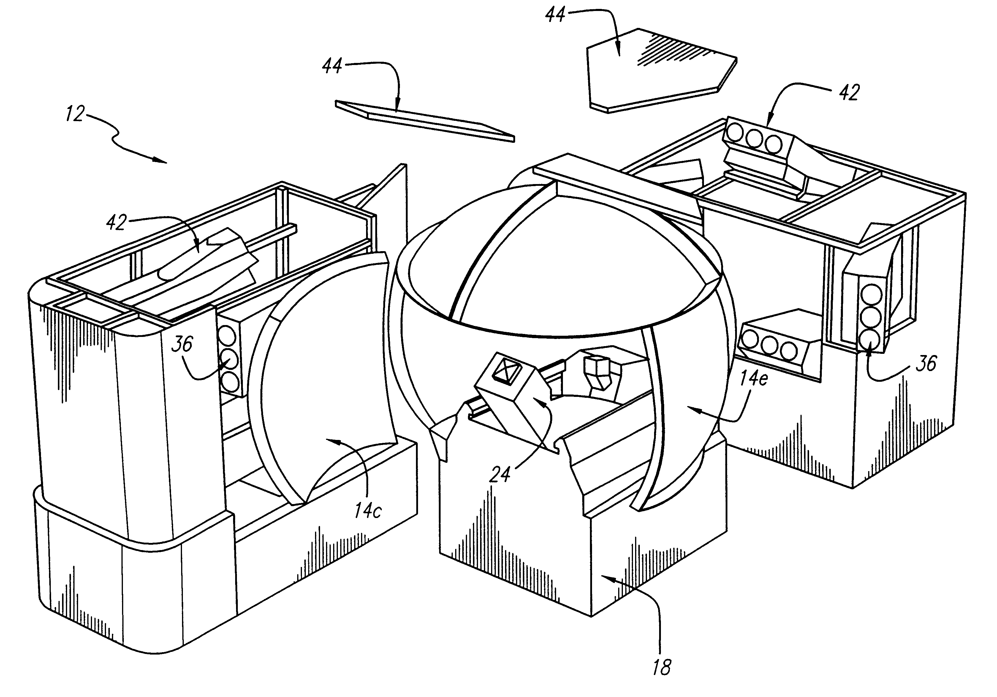
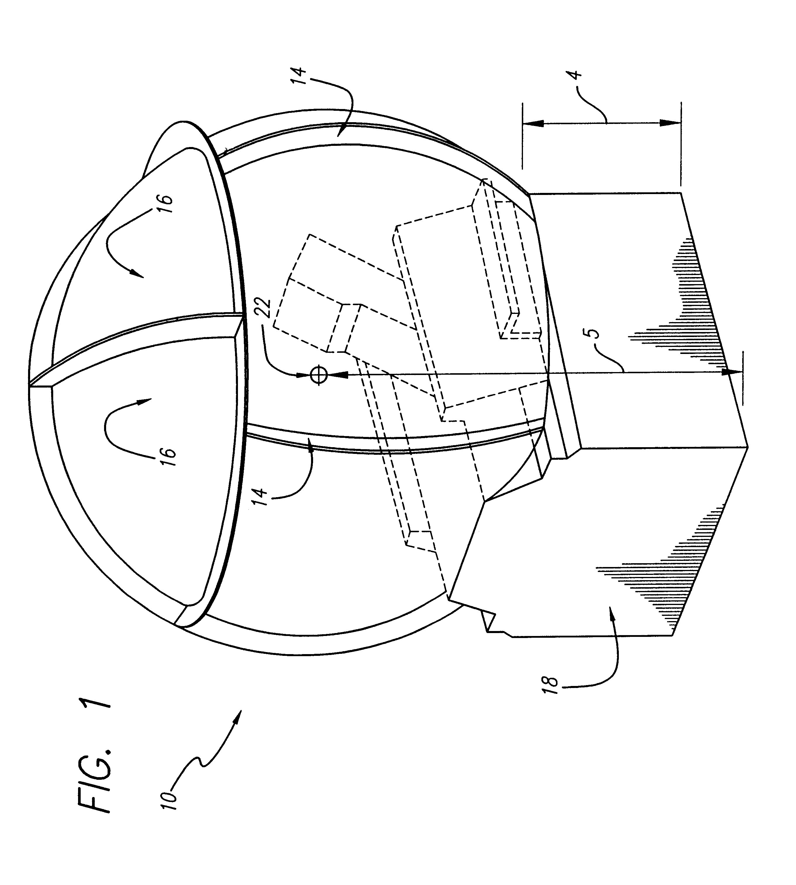
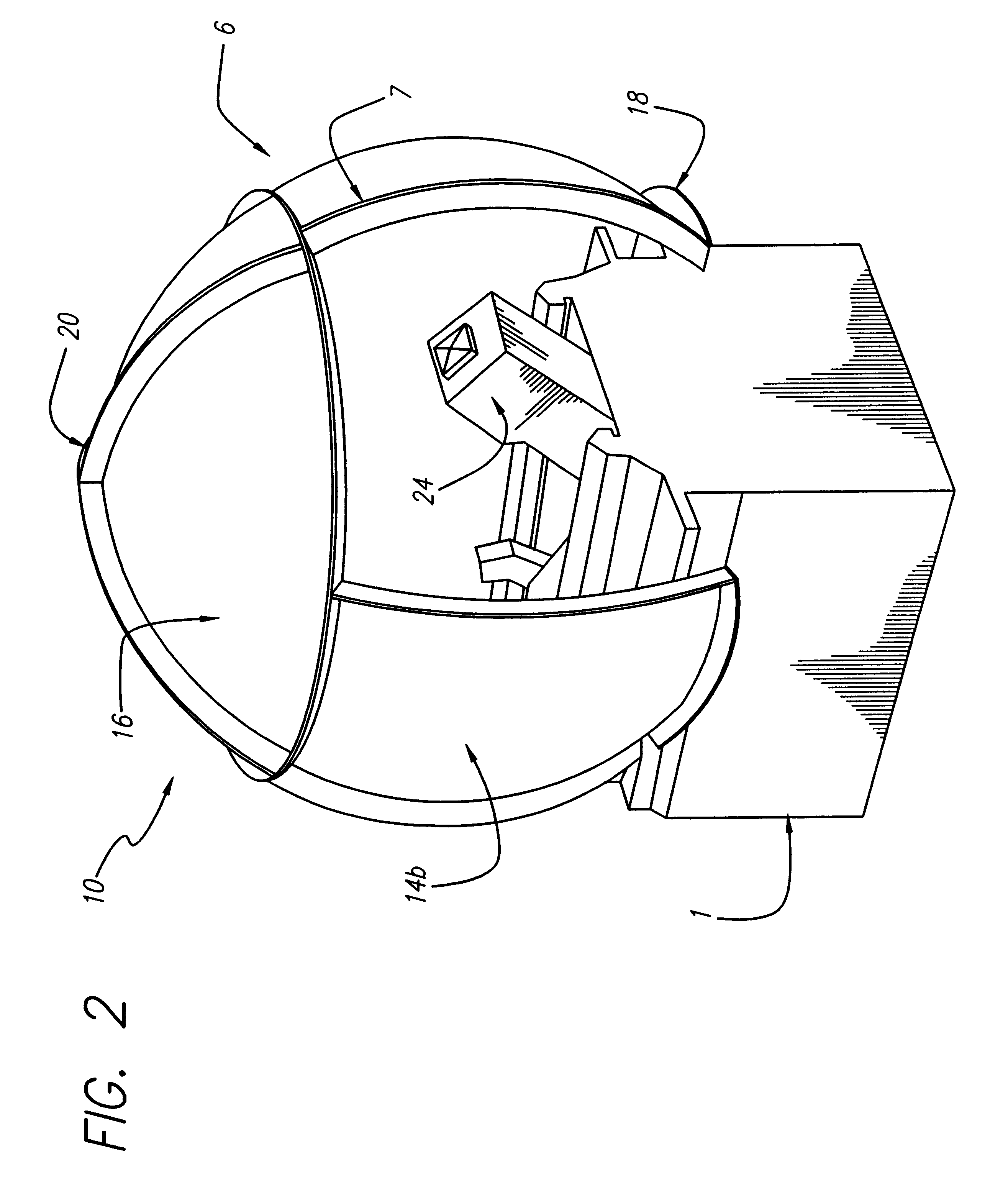
One aspect of the present invention comprises utilization of a laser-based projector in place of conventionally illuminated CRT, LCD, DMD or light valve projectors. Laser-based projectors have greatly expanded focal ranges as compared to such conventional light projectors. For a prototype laser projection system, the laser has a focal depth range of approximately two (2) feet. This means, for example, when using an initial ten (10) foot throw distance, it is possible to move a display panel anywhere between nine (9) and eleven (11) feet from the laser-based projector and still maintain a focused image at all points on the display panel. This advantage is achieved with no cost penalties for specialized...


PUM


Abstract

The present invention is related to a curved surface, real image, laser-based rear projection display system. A plurality of translucent panel members are assembled into a spherical dome assembly. The panels have concave inner surfaces treated with an optical medium to create a diffusion surface onto which the projected visual image is displayed to a design eye point located within the dome. The laser-based projectors have a greatly expanded focal range as compared to conventional sources of illumination. This allows the curved panel members to remain in focus when the dome is moved as much as two (2) relative to the location of the laser projector.

Description

1. Field of the InventionThe present invention relates to real time, curved surface imaging systems. More particularly, the present invention is directed to a laser-based, rear projector imaging system.2. Description of the Related ArtSpherical dome imaging systems have long been used in a variety of applications ranging from planetariums and commercial entertainment systems to military flight simulators. Domed imaging visual systems are capable of generating scenes with a high degree of realism because the scene is presented to the view in many directions at once, not just from a single flat plane as in most conventional imaging systems. The capacity for producing a wide field of view is highly desirable in both commercial and military imaging systems applications.Most conventional dome display systems in use are front projection systems. Like conventional movie theaters, front projection systems employ one or more projectors positioned on the same side of the screen as the viewer ...

Claims


Application Information

Patent Timeline
IPC IPC(8): G03B21/00G09F19/18G09F19/12
CPCG03B21/00G09F19/18G03B21/005
Inventor BEST, LEONARD G.WIGHT, DONALD R.KOCHERT, TIMOTHY J.
Owner RAYTHEON CO
Learn More