Cargo restraint assembly for a vehicle cargo bed

a cargo bed and cargo technology, applied in the field of cargo restraints, can solve the problems of difficult installation and use of restraints, limited utility of the system, and difficult alignment and application of side strips to the side panels, and achieve the effects of maximum flexibility, simple structure, and durabl

Inactive Publication Date: 2001-01-23
ROMPH JOEL
View PDF6 Cites 27 Cited by
  • Summary
  • Abstract
  • Description
  • Claims
  • Application Information

AI Technical Summary

Benefits of technology

The improved cargo restraint assembly for a vehicle cargo bed satisfies all the foregoing needs. The assembly is simple, durable, inexpensive, easy to use and provides a maximum of flexibility in positioning the restraint component of the assembly adjacent to cargo without blocking off the remainder of the cargo bed from use and view.
The cargo stop block has two opposite ends, referred to hereinafter for convenience in describing the block, as the rear and front ends of the block. The block also has a top, an opposite bottom and two opposite sides interconnected thereto. The bottom of the block defines a plurality of spaced parallel grooves extending from one end of the block to the opposite end. The grooves are separated by spaced, parallel depending ribs having opposite sides. The number, size and location of the block ribs and grooves are such that the block can be seated on the bed liner with the block ribs in the bed liner grooves and the block grooves receiving the bed liner ribs. The spacing of the block ribs in the bed liner grooves is such that the block ribs can be moved laterally in the grooves a relatively short distance.

Problems solved by technology

Such restraints are often difficult to install and use.
This system has limited utility, blocking off the entire truck bed area forward of the board.
Moreover, the side strips are difficult to align and apply to the side panels.

Method used


Image

  • Cargo restraint assembly for a vehicle cargo bed
  • Cargo restraint assembly for a vehicle cargo bed

Examples


Embodiment Construction

FIGS. 1 and 2:

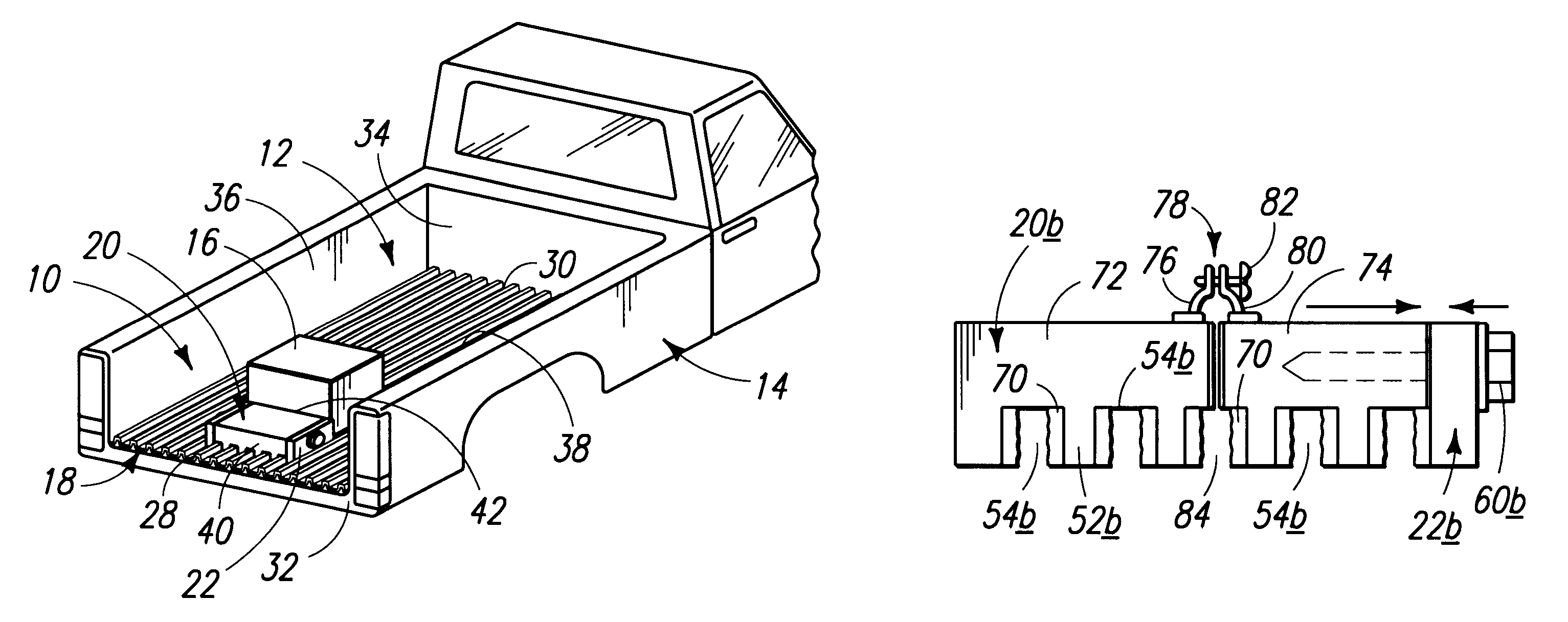
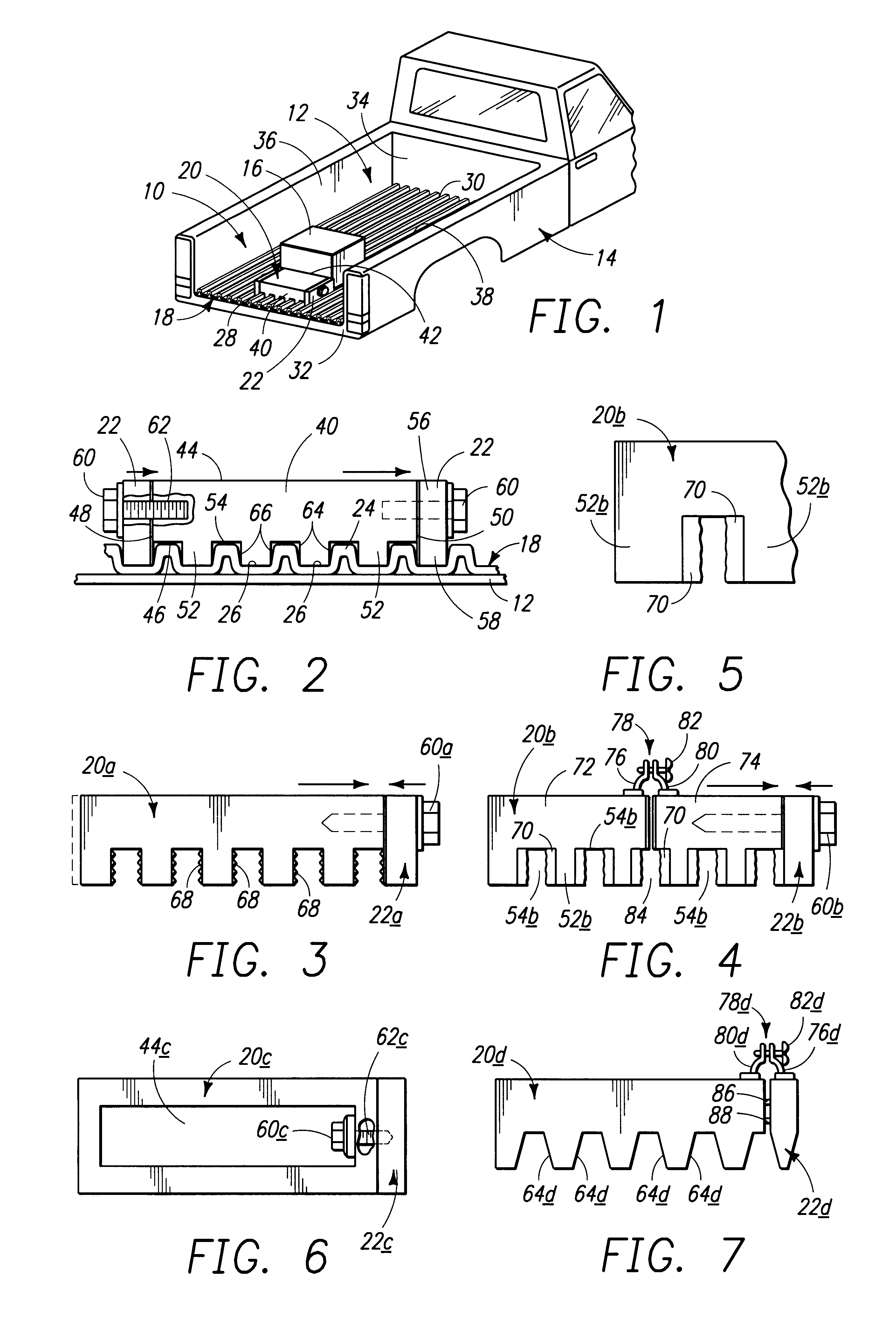
Now referring more specifically to FIGS. 1 and 2 of the drawings, a first preferred embodiment of the improved cargo restraint assembly of the present invention is depicted therein. FIG. 1 shows assembly 10 disposed in the bed 12 of an open bed truck 14, blocking a cargo box 16 from shifting out of bed 12 while still permitting the use of the remainder of the space in bed 12 for other purposes.

Assembly 10 includes a vehicle cargo bed liner 18, stop block 20 and lock 22. Liner 18 has a plurality of spaced parallel upstanding ribs 24 separated by parallel downwardly extending grooves 26. Grooves 26 and ribs 24 run from one end, that is, rear end 28 to the opposite end, that is, front end 30 of liner 18. Liners 18 is oriented in bed 12 so that grooves 26 and ribs 24 run from the rear 32 to the front 34 of bed 12. However, it will be understood that, if desired, grooves 26 and ribs 24 could run from side 36 to side 38 of bed 12.

Stop block 20 has one end , that is, rear end...


PUM


Abstract

The cargo restraint assembly is for a vehicle cargo bed and includes a vehicle cargo bed liner adapted to lie on the floor of the cargo bed. The liner has spaced parallel grooves extending from the rear to the front of the liner and defined by spaced parallel upstanding ribs. The assembly also includes a cargo stop block having a rear end, opposite front end, top, bottom and opposing sides. The block bottom has parallel spaced forwardly extending ribs defining spaced parallel grooves therebetween. The block ribs and grooves are adapted to mate with the grooves and ribs of the bed liner. The assembly further includes a stop block lock which is adapted to draw the block laterally to engage the sides of the block depending ribs with the sides of the upstanding ribs of the bed liner in order to secure the block in place on the bed liner. In one embodiment the lock has a body with a depending rib which fits in a bed liner groove. The lock is adapted to be positioned adjacent a side of the block and includes a transverse draw screw or threaded draw bolt passing into the block. In another embodiment the lock includes a clamp, one portion of which is secured to the lock body and a second portion of which is secured to the block, with a draw screw spanning the two portions of the clamp. In a further embodiment, the block is split about vertically into two parts and the lock is in the form of a clamp having two portions, one portion being connected to one of the block parts and the other portion being connected to the other of the block parts, with a draw screw spanning the two clamp portions. The sides of the depending block ribs can bear teeth to facilitate engagement with the bed liner ribs. Alternatively, the sides of the block ribs can bear flexible resilient strips which act as wedges to help hold the assembly together.

Description

1. Field of the InventionThe present invention generally relates to cargo restraints and more particularly relates to an improved cargo restraint assembly for vehicle cargo beds.2. Prior ArtVarious types of cargo restraints have been proposed for use in the cargo bays of vehicles. One such restraint employs releasable cord ties which hook to the cargo bay and tie down the cargo. Such restraints are often difficult to install and use. Another cargo restraint system is that disclosed in U.S. Pat. No. 4,887,947 to John Bott. That system employs slotted side strips which are aligned with each other and are applied to opposite sides of the inner surfaces of the upraised vertical side panels defining the rear cargo space in a truck. The system also includes an elongated removeable board which spans the width of the cargo bay of the truck and slides into a slot in each of the side strips. This system has limited utility, blocking off the entire truck bed area forward of the board. Moreover...

Claims


Application Information

Patent Timeline
Patent Type & Authority Patents(United States)
IPC IPC(8): B60P7/08B60P7/06
CPCB60P7/0892
Inventor ROMPH, JOEL
Owner ROMPH JOEL
Why Eureka
Try Eureka